TMC5130A DATASHEET (Rev. 1.14 / 2017-MAY-15)
64
Parameter
Description
Setting Comment
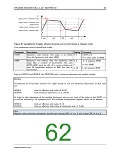
TFD
Fast decay time setting. With CHM=1, these bits 0
slow decay only
(fd3
HSTRT)
& control the portion of fast decay for each chopper
cycle.
1…15
duration of fast decay
phase
OFFSET
(HEND)
Sine wave offset. With CHM=1, these bits control 0…2
negative offset: -3…-1
no offset: 0
the sine wave offset. A positive offset corrects for
zero crossing error.
3
4…15
positive offset 1…12
disfdcc
Selects usage of the current comparator for 0
termination of the fast decay cycle. If current
comparator is enabled, it terminates the fast decay
enable comparator
termination of fast decay
cycle
cycle in case the current reaches a higher negative
value than the actual positive value.
1
end by time only
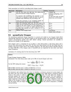
8.3 Random Off Time
In the constant off-time chopper mode, both coil choppers run freely without synchronization. The
frequency of each chopper mainly depends on the coil current and the motor coil inductance. The
inductance varies with the microstep position. With some motors, a slightly audible beat can occur
between the chopper frequencies when they are close together. This typically occurs at a few
microstep positions within each quarter wave. This effect is usually not audible when compared to
mechanical noise generated by ball bearings, etc. Another factor which can cause a similar effect is a
poor layout of the sense resistor GND connections.
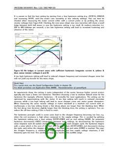
Hint
A common factor, which can cause motor noise, is a bad PCB layout causing coupling of both sense
resistor voltages (please refer layout hints in chapter 31).
To minimize the effect of a beat between both chopper frequencies, an internal random generator is
provided. It modulates the slow decay time setting when switched on by the rndtf bit. The rndtf
feature further spreads the chopper spectrum, reducing electromagnetic emission on single
frequencies.
Parameter
Description
Setting Comment
This bit switches on a random off time generator,
which slightly modulates the off time TOFF using
a random polynomial.
rndtf
0
1
disable
random modulation
enable
www.trinamic.com

 TRINAMIC [ TRINAMIC MOTION CONTROL GMBH & CO. KG. ]