TMC4361 DATASHEET (Rev. 2.68 / 2015-Apr-14) Preliminary
8
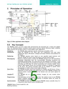
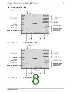
3 Sample Circuits
The sample circuits show the connection of external components.
HOME STOPL STOPR
NSCSIN
NSCSDRV_SDO
SDODRV_SCLK
SDIIN
SPI Control Interface
SPI Output Interface
to Motor Driver
to Microcontroller
SCKIN
SCKDRV_NSDO
SDIDRV_NSCLK
SDOIN
STPOUT_PWMA
DIRPOUT_PWMB
Step/Dir Interface
to Motor Driver
Ext. Clock
CLK_EXT
START
TMC4361
Start Signal
Input or Output
STDBY_CLK
Standby Clock Output
A_SCLK
ANEG_NSCLK
B_SDI
BNEG_NSDI
N
Interrupt Output
Target Reached Output
Optional Inv. Reset Input
Emergency Stop Switch
INTR
Encoder Input Interface
for incremental ABN or
serial BiSS/SSI/SPI
TARGET_REACHED
NRST
NFREEZE
VCC
NNEG
GND
TEST_MODE VDD1V8 VDD1V8
100 nF
100 nF
100 nF
+3.3 V
Figure 3.1 How to connect the TMC4361 (VCC = 3.3V)
Reference Switches
HOME STOPL STOPR
NSCSIN
NSCSDRV_SDO
SDODRV_SCLK
SDIIN
SPI Control Interface
SPI Output Interface
to Motor Driver
to Microcontroller
SCKIN
SCKDRV_NSDO
SDIDRV_NSCLK
SDOIN
STPOUT_PWMA
DIRPOUT_PWMB
Step/Dir Interface
to Motor Driver
Ext. Clock
CLK_EXT
START
TMC4361
Start Signal
Input or Output
STDBY_CLK
Standby Clock Output
A_SCLK
ANEG_NSCLK
B_SDI
BNEG_NSDI
N
Interrupt Output
Target Reached Output
Optional Inv. Reset Input
Emergency Stop Switch
INTR
Encoder Input Interface
for incremental ABN or
serial BiSS/SSI/SPI
TARGET_REACHED
NRST
NFREEZE
VCC
NNEG
GND
TEST_MODE VDD1V8 VDD1V8
100 nF
100 nF
100 nF
+5 V
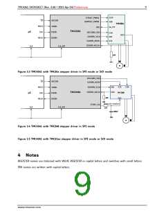
Figure 3.2 How to connect the TMC4361 (VCC = 5V)
www.trinamic.com

 TRINAMIC [ TRINAMIC MOTION CONTROL GMBH & CO. KG. ]