TMC4361 DATASHEET (Rev. 2.68 / 2015-Apr-14) Preliminary
7
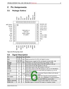
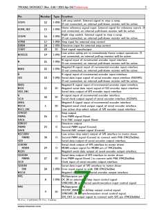
Pin
Number Type Function
Left stop switch. External signal to stop a ramp.
If not connected, an internal pull-down resistor will be active.
STOPL
12
13
14
I (PD)
I (PD)
I (PD)
Home reference signal input. External signal for reference search. If
not connected, an internal pull-down resistor will be active.
HOME_REF
STOPR
Right stop switch. External signal to stop a ramp.
If not connected, an internal pull-down resistor will be active.
STPIN
DIRIN
START
17
18
20
I (PD) Step input for external step control
I (PD) Direction input for external step control
IO Start signal input/output
Low active safety pin to immediately freeze output operations. If
not connected, an internal pull-up resistor will be active.
NFREEZE
N
19
21
22
I (PU)
N signal input of incremental encoder input interface
If not connected, an internal pull-down resistor will be active.
I (PD)
Negated N signal input of incremental encoder input interface
If not connected, an internal pull-down resistor will be active.
NNEG
I (PD)
B
SDI
B signal input of incremental encoder input interface.
I (PD) Serial data input signal of serial encoder input interface (SSI/SPI).
If not connected, an internal pull-down resistor will be active.
10
BNEG
NSDI
SDO_ENC
Negated B signal input of incremental encoder input interface.
IO Negated serial data input signal of SSI encoder input interface
Serial data output of SPI encoder input interface.
11
40
1
A
SCLK
A signal input of incremental encoder interface.
Serial clock output signal of serial encoder interface (SSI/SPI).
IO
ANEG
NSCLK
NSCS_ENC
Negated A signal input of incremental encoder interface.
IO Negated serial clock output signal of serial encoder interface.
Low active chip select output of SPI encoder input interface.
STPOUT
PWMA
DACA
Step output.
First PWM signal (Sine).
First DAC output signal (Sine).
24
23
30
29
27
28
8
O
O
O
O
DIROUT
PWMB
DACB
Direction output.
Second PWM signal (Cosine).
Second DAC output signal (Cosine).
NSCSDRV
PWMB
SDO
Low active chip select output of SPI interface to motor driver.
Second PWM signal (Cosine) to connect with PHB (TMC23x/24x).
Serial data output of serial encoder output interface.
SCKDRV
MDBN
NSDO
Serial clock output of SPI interface to motor driver.
MDBN output signal for MDBN pin of TMC23x/24x.
Negated serial data output of serial encoder output interface.
SDODRV
PWMA
SCLK
Serial data output of SPI interface to motor driver.
IO First PWM signal (Sine) ) to connect with PHA (TMC23x/24x).
Clock input of serial encoder output interface.
SDIDRV
ERR
NSCLK
Serial data input of SPI interface to motor driver.
I (PD) Error input signal to with ERR (TMC23x/24x).
Negated clock input of serial encoder output interface
MP1
Multipurpose pin 1:
I (PD) DC_IN as external dcStep input control signal
SYNCHRO_IN as external synchronization input control signal
MP2
Multipurpose pin 2:
DCSTEP_ENABLE as dcStep output control signal.
SYNCHRO_IN as synchronization inout control signal.
9
IO
SPE_OUT as output signal to connect with SPE pin (TMC23x/24x)
PD: if n.c. pull-down; PU: if n.c. pull-up
www.trinamic.com

 TRINAMIC [ TRINAMIC MOTION CONTROL GMBH & CO. KG. ]