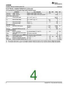
UCD9090
SLVSA30A –APRIL 2011–REVISED AUGUST 2011
www.ti.com
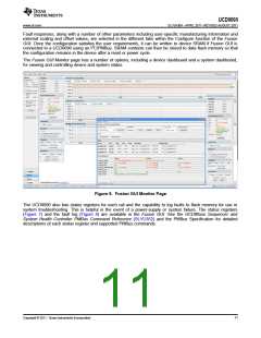
graphical user interface (GUI) offers an intuitive I2C/PMBus interface to the device. It allows the design engineer
to configure the system operating parameters for the application without directly using PMBus commands, store
the configuration to on-chip nonvolatile memory, and observe system status (voltage, etc). Fusion Digital Power
Designer is referenced throughout the data sheet as Fusion GUI and many sections include screenshots. The
Fusion GUI can be downloaded from www.ti.com.
PMBUS INTERFACE
The PMBus is a serial interface specifically designed to support power management. It is based on the SMBus
interface that is built on the I2C physical specification. The UCD9090 supports revision 1.1 of the PMBus
standard. Wherever possible, standard PMBus commands are used to support the function of the device. For
unique features of the UCD9090, MFR_SPECIFIC commands are defined to configure or activate those features.
These commands are defined in the UCD90xxx Sequencer and System Health Controller PMBUS Command
Reference (SLVU352). The most current UCD90xxx PMBus™ Command Reference can be found within the TI
Fusion Digital Power Designer software via the Help Menu (Help, Documentation & Help Center, Sequencers
tab, Documentation section).
This document makes frequent mention of the PMBus specification. Specifically, this document is PMBus Power
System Management Protocol Specification Part II – Command Language, Revision 1.1, dated 5 February 2007.
The specification is published by the Power Management Bus Implementers Forum and is available from
www.pmbus.org.
The UCD9090 is PMBus compliant, in accordance with the Compliance section of the PMBus specification. The
firmware is also compliant with the SMBus 1.1 specification, including support for the SMBus ALERT function.
The hardware can support either 100-kHz or 400-kHz PMBus operation.
THEORY OF OPERATION
Modern electronic systems often use numerous microcontrollers, DSPs, FPGAs, and ASICs. Each device can
have multiple supply voltages to power the core processor, analog-to-digital converter or I/O. These devices are
typically sensitive to the order and timing of how the voltages are sequenced on and off. The UCD9090 can
sequence supply voltages to prevent malfunctions, intermittent operation, or device damage caused by improper
power up or power down. Appropriate handling of under- and overvoltage faults can extend system life and
improve long term reliability. The UCD9090 stores power supply faults to on-chip nonvolatile flash memory for aid
in system failure analysis.
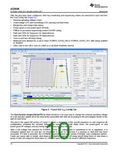
System reliability can be improved through four-corner testing during system verification. During four-corner
testing, the system is operated at the minimum and maximum expected ambient temperature and with each
power supply set to the minimum and maximum output voltage, commonly referred to as margining. The
UCD9090 can be used to implement accurate closed-loop margining of up to 10 power supplies.
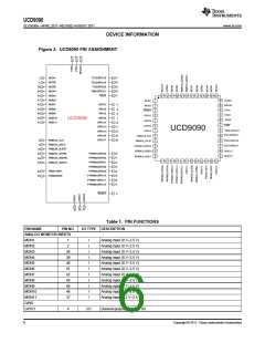
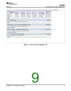
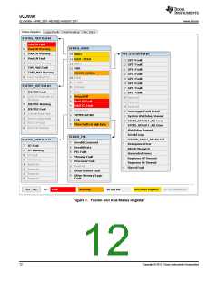
The UCD9090 10-rail sequencer can be used in a PMBus- or pin-based control environment. The TI Fusion GUI
provides a powerful but simple interface for configuring sequencing solutions for systems with between one and
10 power supplies using 10 analog voltage-monitor inputs, two GPIs and 21 highly configurable GPIOs. A rail
includes voltage, a power-supply enable and a margining output. At least one must be included in a rail
definition. Once the user has defined how the power-supply rails should operate in a particular system, analog
input pins and GPIOs can be selected to monitor and enable each supply (Figure 4).
8
Copyright © 2011, Texas Instruments Incorporated

 TI [ TEXAS INSTRUMENTS ]