UCD9090
www.ti.com
SLVSA30A –APRIL 2011–REVISED AUGUST 2011
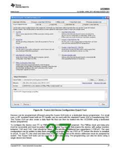
Figure 29. Fusion GUI Device Configuration Export Tool
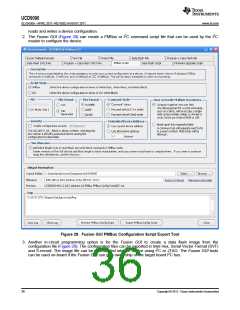
Devices can be programmed off-board using the Fusion GUI tools or a dedicated device programmer. For small
runs, a ZIF socketed board with an I2C header can be used with the standard Fusion GUI or manufacturing GUI.
The Fusion GUI can also create a data flash file that can then be loaded into the UCD9090 using a dedicated
device programmer.
To configure the device over I2C or PMBus, the UCD9090 must be powered. The PMBus clock and data pins
must be accessible and must be pulled high to the same VDD supply that powers the device, with pullup resistors
between 1 kΩ and 2 kΩ. Care should be taken to not introduce additional bus capacitance (<100 pF). The user
configuration can be written to data flash using a gang programmer via JTAG or I2C before the device is installed
in circuit. To use I2C, the clock and data lines must be multiplexed or the device addresses must be assigned by
socket. The Fusion GUI tools can be used for socket addressing. Pre-programming can also be done using a
single device test fixture.
Copyright © 2011, Texas Instruments Incorporated
37

 TI [ TEXAS INSTRUMENTS ]