UCD90320
www.ti.com.cn
ZHCSFI3B –AUGUST 2016–REVISED MAY 2019
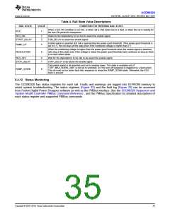
Table 4. Rail State Value Descriptions
RAIL STATE
VALUE
CONDITION FOR ENTERING RAIL STATE
When a turn-ON condition is not met, or when rail is shut down due to a fault, or when the rail is waiting for
the turn-ON period to resequence
IDLE
1
SEQ_ON
2
3
Waits for the dependency to be met to assert the enable signal
TON_DELAY to assert the enable signal
START_DELAY
Enable signal is asserted and rail is approaching the power good threshold. If the power good threshold is
set to 0 V, the rail stays at this state even if the monitored voltage is higher than 0 V.
RAMP_UP
4
When the monitoring voltage is higher than the power good threshold when the enable signal is asserted,
rails stay at this state even if the voltage is below the power good threshold and continues as long as there
is no fault action taken.
REGULATION
5
SEQ_OFF
6
7
Wait for the dependency to be met to de-assert the enable signal
TOFF_DELAY to de-assert the enable signal
STOP_DELAY
The enable signal is de-asserted and rail is ramping down. This state is available only if
TOFF_MAX_WARN_LIMIT is not set to unlimited, or if the turn-off sequence is triggered by a fault action.
The rail must not be under fault retry sequence to show this RAMP_DOWN state. Otherwise, the IDLE
state is present.
RAMP_DOWN
8
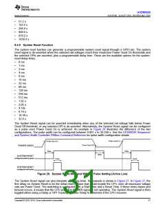
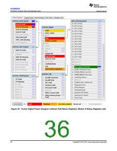
8.4.12 Status Monitoring
The UCD90320 has status registers for each rail. Faults and warnings are logged into EEPROM memory to
assist system troubleshooting. The status registers (Figure 32) and the fault log (Figure 33) can be accessed
from Fusion Digital Power Designer software as well as the PMBus interface. See the UCD90320 Sequencer and
System Health Controller PMBus Command Reference , and the PMBus Specification for detailed descriptions of
each status register and supported PMBus commands.
Copyright © 2016–2019, Texas Instruments Incorporated
35

 TI [ TEXAS INSTRUMENTS ]