UCD90320
ZHCSFI3B –AUGUST 2016–REVISED MAY 2019
www.ti.com.cn
Power Good On
POWER GOOD
Watchdog
Reset Time
Watchdog
Start Time
Watchdog
Start Time
WDI
Delay
Watchdog
Reset Time
SYSTEM RESET
Delay or
GPI Tracking Release Delay
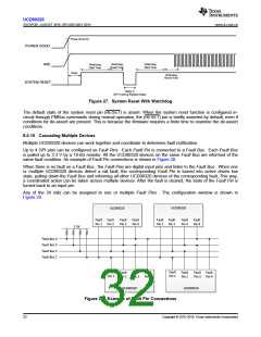
Figure 27. System Reset With Watchdog
The default state of the system reset pin (RESET) is assert. When the system reset function is configured in-
circuit through PMBus commands during normal operation, the (RESET) pin is briefly asserted by default, even if
conditions for de-assert are present. This is because the firmware requires a finite time to examine the de-assert
conditions.
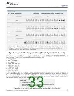
8.4.10 Cascading Multiple Devices
Multiple UCD90320 devices can work together and coordinate to determine fault notification.
Up to 4 GPI pins can be configured as Fault Pins . Each Fault Pin is connected to a Fault Bus . Each Fault Bus
is pulled up to 3.3 V by a 10-kΩ resistor. All the UCD90320 devices on the same Fault Bus are informed of the
same fault condition. An example of Fault Pin connections is shown in Figure 28.
When there is no fault on a Fault Bus , the Fault Pins are digital input pins and listen to the Fault Bus . When one
or multiple UCD90320 devices detect a rail fault, the corresponding Fault Pin is turned into active driven low
state, pulling down the Fault Bus and informing all other UCD90320 devices of the corresponding fault. This way,
a coordinated action can be taken across multiple devices. After the fault is cleared, the state of the Fault Pin is
turned back to an input pin.
Any of the 24 rails can be assigned to one or multiple Fault Pins . The configuration window is shown in
Figure 29.
UCD90320
UCD90320
Fault Fault
Pin 1 Pin 2
Fault
Pin 3
Fault
Pin 4
Fault Fault
Pin 1 Pin 2
Fault
Pin 3
Fault
Pin 4
3.3V
Fault Bus 4
Fault Bus 3
Fault Bus 2
Fault Bus 1
Fault
Pin 1
Fault
Pin 1
Fault
Pin 2
Fault Fault
Pin 3 Pin 4
Fault
Pin 2
Fault Fault
Pin 3 Pin 4
UCD90320
UCD90320
Figure 28. Example of Fault Pin Connections
32
Copyright © 2016–2019, Texas Instruments Incorporated

 TI [ TEXAS INSTRUMENTS ]