UCD90320
www.ti.com.cn
ZHCSFI3B –AUGUST 2016–REVISED MAY 2019
•
•
•
•
•
•
51.2 s
102.4 s
204.8 s
409.6 s
819.2 s
1638.4 s
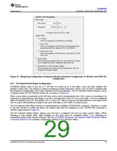
8.4.9 System Reset Function
The system reset function can generate a programmable system reset signal through a GPIO pin. The system
reset signal is de-asserted when the selected rail voltages reach their respective Power Good On thresholds and
the selected GPIs are asserted, plus a programmable delay time. These are the available options for the system-
reset delay times.
•
•
•
•
•
•
•
•
•
•
•
•
•
•
•
•
•
0 ms
1 ms
2 ms
4 ms
8 ms
16 ms
32 ms
64 ms
128 ms
256 ms
512 ms
1.02 s
2.05 s
4.10s
8.19 s
16.38 s
32.8 s
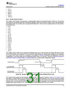
The System Reset signal can be asserted immediately when any of the selected rail voltage falls below Power
Good Off threshold, or any selected GPI is de-asserted. Alternatively, the System Reset signal can be configured
as a pulse once Power Good On is achieved. An example in Figure 26 illustrates the difference of the two
configurations. The pulse width can be configured between 0.001 s to 32.256 s. See the UCD90320 Sequencer
and System Health Controller PMBus Command Reference for pulse width configuration details.
Power Good On
Power Good On
Power Good Off
POWER GOOD
Delay
Delay
Delay
SYSTEM RESET
configured without pulse
Pulse
Pulse
SYSTEM RESET
configured with pulse
Figure 26. System Reset With and Without Pulse Setting (Active Low)
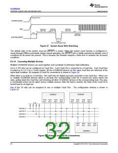
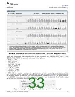
The System Reset signal can also integrate watchdog timer. An example is shown in Figure 27. In Figure 27, the
first delay on System Reset is for the initial reset release that would enable the CPU once all necessary voltage
rails are Power Good. The watchdog is configured with a Start Time and a Reset Time. If these times expire and
timeout occurs, it means that the CPU providing the WDI signal is not operating. The System Reset signal is then
toggled either using a Delay or GPI Tracking Release Delay to determine if the CPU recovers.
Copyright © 2016–2019, Texas Instruments Incorporated
31

 TI [ TEXAS INSTRUMENTS ]