UCD90320
www.ti.com.cn
ZHCSFI3B –AUGUST 2016–REVISED MAY 2019
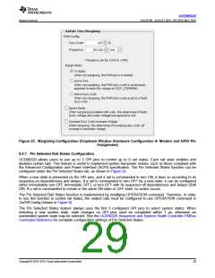
Figure 23. Margining Configuration Dropdown Window (Hardware Configuration ► Monitor and GPIO Pin
Assignment)
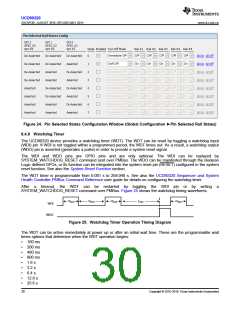
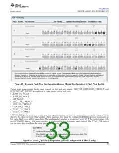
8.4.7 Pin Selected Rail States Configuration
UCD90320 allows users to use up to 3 GPI pins to control up to 8 rail states. Each rail state enables and
disables certain rails. This feature is useful to implement system low-power modes, such as those compliant with
the Advanced Configuration and Power Interface (ACPI) specification. The Pin Selected States function can be
configured under the Pin Selected States tab, as shown in Figure 24.
When a new state is presented on the GPI pins, and a rail is commanded to turn ON, it does so according to its
sequence-on dependencies and delays. If a rail is commanded to turn OFF by a new state, it can be configured
either immediately turn-OFF (Immediate OFF), or turn-OFF with its sequence-off dependencies and delays (Soft
Off). If a rail is commanded to remain in the same ON state or OFF state, no action occurs.
The Pin Selected Rail States function is implemented by modifying OPERATION command. Therefore, in order
to use this function to control rail states, the related rails must be configured to use OPERATION command in
On/Off Config (shown in Figure 6).
The Pin Selected States feature always uses the first 3 configured GPI pins to select system states. When
selecting a new system state, state changes on GPI pins must be completed within 1 µs, otherwise an
unintended system state may be selected. See the UCD90320 Sequencer and System Health Controller PMBus
Command Reference for complete configuration settings of Pin Selected States.
Copyright © 2016–2019, Texas Instruments Incorporated
29

 TI [ TEXAS INSTRUMENTS ]