ꢀꢁꢁ ꢂ ꢃꢄ ꢅ ꢆ ꢀꢁꢁ ꢂ ꢃꢄ ꢇ ꢆ ꢀ ꢁꢁ ꢂꢃ ꢄꢄ
ꢀꢁꢁ ꢈ ꢃꢄ ꢅ ꢆ ꢀꢁꢁ ꢈ ꢃꢄ ꢇ ꢆ ꢀ ꢁꢁ ꢈꢃ ꢄꢄ
SLUS499A – NOVEMBER 2001 – REVISED JANUARY 2002
APPLICATION INFORMATION
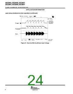
burst dimming with the OPEN/SD pin
A burst dimming technique can be used with CCFLs when a wide dimming range is required, this technique can
also yield better efficiency at light loads. Burst dimming is implemented by running the lamp at full current when
on, where the on/off duty factor is controlled a low frequency to provide dimming. In order to prevent visible
flicker, the burst frequency needs to be set higher than 80 Hz.
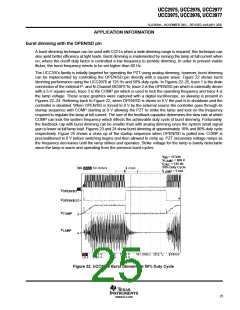
The UCC397x family is initially targeted for operating the PZT using analog dimming, however, burst dimming
can be implemented by controlling the OPEN/SD pin directly with a square wave. Figure 22 shows burst
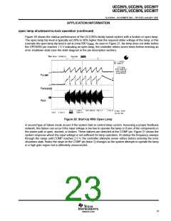
dimming performance using the UCC3976 at 125 Hz and 50% duty cycle. In Figures 22–25, trace 1 is the drain
connection of the external P- and N-Channel MOSFETs, trace 2 is the OPEN/SD pin which is externally driven
with a 5-V square wave, trace 3 is the COMP pin which is used to lock the operating frequency and trace 4 is
the lamp voltage. These scope graphics were captured with a digital oscilloscope, so aliasing is present in
Figures 22–24. Referring back to Figure 22, when OPEN/SD is driven to 5 V the part is in shutdown and the
controller is disabled. When OPEN/SD is forced to 0 V by the external source the controller goes through its
startup sequence with COMP starting at 0 V allowing the PZT to strike the lamp and lock on the frequency
required to regulate the lamp at full current. The size of the feedback capacitor determines the slew rate at which
COMP can lock the system frequency which effects the achievable duty cycle of burst dimming. Fortunately,
the feedback cap with burst dimming can be smaller than with analog dimming since the system small signal
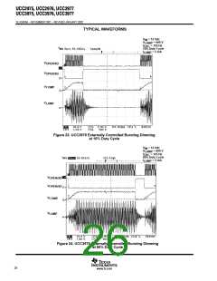
gain is lower at full lamp load. Figures 23 and 24 show burst dimming at approximately 10% and 90% duty cycle
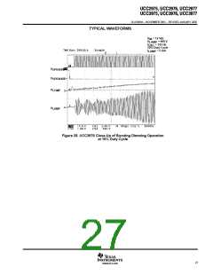
respectively. Figure 25 shows a close up of the startup sequence when OPEN/SD is pulled low. COMP is
preconditioned to 0 V before switching begins and then allowed to ramp up. PZT secondary voltage ramps as
the frequency decreases until the lamp strikes and operates. Strike voltage for the lamp is barely detectable
since the lamp is warm and operating from the previous burst cycles.
V
V
= 12 Vdc
IN
LAMP
= 125 Hz
= 600 V
f
OSC
50% Duty Cycle
= 5 mA
I
LAMP
V
V
OPEN/SD
OPEN/SD
V
COMP
LAMP
V
Figure 22. UCC3976 Burst Dimming at 50% Duty Cycle
25
www.ti.com

 TI [ TEXAS INSTRUMENTS ]