UCC28951
www.ti.com.cn
ZHCSIQ7A –AUGUST 2018 –REVISED DECEMBER 2021
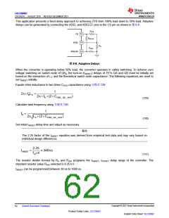
This application presents a fixed delay approach to achieving ZVS from 100% load down to 50% load. Adaptive
delays can be generated by connecting the ADEL and ADELEF pins to the CS pin as shown in 图8-8 .
RAHI
CS 15
RAEFHI
ADEL 14
RA
RAEF
ADELEF 13
图8-8. Adaptive Delays
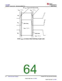
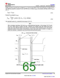
When the converter is operating below 50% load, the converter operates in valley switching. To achieve zero
voltage switching on switch node of QBd, the turn-on (tABSET) delays of FETs QA and QB must be initially set
based on the interaction of LS and the theoretical switch node capacitance. The following equations are used to
set tABSET initially.
Equate shim inductance to two times COSS capacitance using 方程式129:
1
2p´ fRLS =
2p´ fR ´(2´COSS _ QA _ AVG
)
(129)
(130)
Calculate tank frequency using 方程式130:
1
fR =
2p LS ´(2´COSS _ QA _ AVG
)
Set initial tABSET delay time and adjust as necessary.
备注
The 2.25 factor of the tABSET equation was derived from empirical test data and may vary based on
individual design differences.
2.25
tABSET
=
» 346ns
f R´4
(131)
The resistor divider formed by RA and RAHI programs the tABSET, tCDSET delay range of the controller. The
standard resistor value RAHI selected is 8.25 kΩ.
tABSET can be programmed between 30 ns to 1000 ns.
Copyright © 2023 Texas Instruments Incorporated
English Data Sheet: SLUSDB2
62
Submit Document Feedback
Product Folder Links: UCC28951

 TI [ TEXAS INSTRUMENTS ]