UCC28951
www.ti.com.cn
ZHCSIQ7A –AUGUST 2018 –REVISED DECEMBER 2021
Calculate double pole frequency of GCO(f):
F
SW
fPP
»
= 50kHz
2
(119)
(120)
Calculate angular velocity:
S(f) = 2p´ j´ f
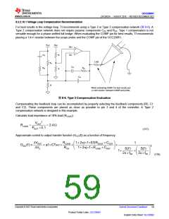
Compensate the voltage loop with Type 2 feedback network. The following transfer function is the compensation
gain as a function of frequency (GC(f)):
DVC
2pj´ f ´R5´C2 +1
GC(f) =
=
2pj´ f ´C2´C1´R5
DVOUT
æ
ö
2pj´ f ´ C2 + C1 R4
+1
(
)
ç
è
÷
C2 + C1
ø
(121)
Calculate voltage loop feedback resistor (R5) based on the crossing the voltage loop (fC) over at a 10th of the
double pole frequency (fPP):
fPP
fC =
= 5kHz
10
(122)
(123)
R4
f
R5 =
» 27.9kW
æ
PP ö
GCO
ç
÷
10
è
ø
The standard resistor selcted for R5 is 27.4 kΩ.
Calculate the feedback capacitor (C2) to give added phase at crossover:
1
C2 =
» 5.8nF
fC
5
2´ p´R5´
(124)
The standard capacitance value (C2) selected for the design is 5.6 nF.
Put a pole at two times fC:
1
C1=
» 580pF
2´ p´R5´ fC ´ 2
(125)
(126)
The standard capacitance value (C1) selected for the design is 560 pF.
Use 方程式126 to calculate the loop gain as a function of frequency (TV(f)) in dB.
T dB(f) = 20log G (f)´G (f)
(
)
V
C
CO
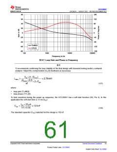
Plot a theoretical loop gain and phase to graphically confirm loop stability. The theoretical loop gain crosses over
at roughly 3.7 kHz with a phase margin of greater than 90 degrees.
Copyright © 2023 Texas Instruments Incorporated
English Data Sheet: SLUSDB2
60
Submit Document Feedback
Product Folder Links: UCC28951

 TI [ TEXAS INSTRUMENTS ]