UCC28951
www.ti.com.cn
ZHCSIQ7A –AUGUST 2018 –REVISED DECEMBER 2021
2
é
I
ù
ú
ú
û
I
-I
MP
(
)
PP
ê
I
=
D
(
´I
+
» 2.5A
)
PRMS1
MAX
PP MP
ê
3
ë
(39)
(40)
DI
1
æ
ö
LOUT
IMP2 = IPP -
» 3.0A
ç
÷
2
a1
è
ø
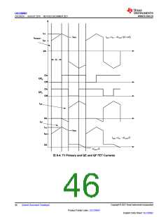
T1 Primary RMS (IPRMS1) current when energy is being delivered to the secondary (see 方程式41).
2
é
I
ù
ú
ú
û
I
-I
MP
(
)
PP
ê
I
=
D
(
´I
+
» 2.5A
)
PRMS1
MAX
PP MP
ê
3
ë
(41)
T1 Primary RMS (IPRMS2) current when the converter is free wheeling. This is calculated in 方程式42:
2
é
ù
ú
û
I -I
(
)
PP
MP2
ê
IPRMS2
=
1-D
(
I ´I
+
» 1.7A
)
ê PP
ú
MAX
MP2
3
ë
(42)
(43)
The total T1 primary RMS current (IPRMS) is calculated using 方程式43:
2
2
IPRMS = IPRMS1 +IPRMS2 » 3.1A
For this design, a Vitec™ transformer was selected for part number 75PR8107 with the following specifications:
• a1 = 21
• LMAG = 2.8 mH
• measured leakage inductance on the Primary (LLK) is 4 µH
• transformer Primary DC resistance (DCRP) is 0.215 Ω
• transformer Secondary DC resistance (DCRS) is 0.58 mΩ
• estimated transformer core losses (PT1) calculated in 方程式44 are twice the copper loss (which is an
estimate and the total losses may vary based on magnetic design)
P » 2´ I
(
T1
2 ´DCRP + 2´ISRMS2 ´DCRS » 7.0W
PRMS
)
(44)
(45)
Calculate remaining power budget using 方程式45:
P
= P
-P » 38.1W
BUDGET
BUDGET T1
8.2.2.3 QA, QB, QC, QD FET Selection
In this design to meet efficiency and voltage requirements 20 A, 650 V, CoolMOS FETs from Infineon are chosen
for QA..QD.
The FET drain to source on resistance is:
Rds(on)QA = 0.220W
(46)
The FET Specified COSS is:
Copyright © 2023 Texas Instruments Incorporated
English Data Sheet: SLUSDB2
48
Submit Document Feedback
Product Folder Links: UCC28951

 TI [ TEXAS INSTRUMENTS ]