UCC28180
www.ti.com
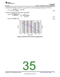
SLUSBQ5A –NOVEMBER 2013–REVISED NOVEMBER 2013
Output Voltage Set Point
For low power dissipation and minimal contribution to the voltage set point, it is recommended to use 1 MΩ for
the top voltage feedback divider resistor, RFB1. Multiple resistors in series are used due to the maximum
allowable voltage across each. Using the internal 5-V reference, VREF, the bottom divider resistor, RFB2, is
selected to meet the output voltage design goals.
VREFRFB1
RFB2
=
VOUT - VREF
(68)
(69)
5 V ´1MW
RFB2
=
= 13.04kW
390 V - 5 V
A standard value 13-kΩ resistor for RFB2 results in a nominal output voltage set point of 391 V.
An output over voltage is detected when the output voltage exceeds its nominal set-point level by 5%, as
measured when the voltage at VSENSE is 105% of the reference voltage, VREF. At this threshold, the enhanced
dynamic response (EDR) is triggered and the non-linear gain to the voltage error amplifier will increase the
transconductance to VCOMP and quickly return the output to its normal regulated value. This EDR threshold
occurs when the output voltage reaches the VOUT(ovd) level:
VOVD = 1.05 VREF = 1.05 ´5 V = 5.25 V
(70)
æ
OVD ç
è
ö
÷
ø
RFB1 + RFB2
VOUT(ovd) = V
RFB2
(71)
(72)
æ
ç
è
ö
÷
ø
1MW +13kW
13kW
VOUT(ovd) = 5.25 V ´
= 410.7 V
In the event of an extreme output over voltage event, the GATE output will be disabled if the output voltage
exceeds its nominal set-point value by 9%. The output voltage, VOUT(ovp), at which this protection feature is
triggered is calculated as follows:
æ
REF ç
è
ö
÷
ø
RFB1 + RFB2
VOUT(ovp) = 1.09 ´ V
= 426.4 V
RFB2
(73)
An output under voltage is detected when the output voltage falls below 5% below its nominal set-point as
measured when the voltage at VSENSE is 95% of the reference voltage, VREF
:
VUVD = 0.95 VREF = 0.95 ´5 V = 4.75 V
(74)
æ
UVD ç
è
ö
÷
ø
RFB1 + RFB2
VOUT(uvp) = V
RFB2
(75)
(76)
æ
ç
è
ö
÷
ø
1MW +13kW
13kW
VOUT(uvp) = 4.75 V ´
= 371.6 V
A small capacitor on VSENSE must be added to filter out noise. Limit the value of the filter capacitor such that
the RC time constant is limited to approximately 10 µs so as not to significantly reduce the control response time
to output voltage deviations.
10ms
CVSENSE
=
= 769pF
RFB2
(77)
The closest standard value of 820 pF was used on VSENSE for a time constant of 10.66 µs.
Copyright © 2013, Texas Instruments Incorporated
Submit Documentation Feedback
31
Product Folder Links :UCC28180

 TI [ TEXAS INSTRUMENTS ]