UCC28180
SLUSBQ5A –NOVEMBER 2013–REVISED NOVEMBER 2013
www.ti.com
Loop Compensation
The current loop is compensated first by determining the product of the internal loop variables, M1M2, using the
internal controller constants K1 and KFQ. Compensation is optimized maximum load and nominal input voltage,
115 VAC is used for the nominal line voltage for this design:
IOUT(max)VO2UT 2.5RSENSEK1
M1M2 =
hVI2N_ RMSKFQ
(78)
1
KFQ
=
=
fSW
1
KFQ
= 8.475ms
118kHz
K1 = 7
(79)
(80)
0.923 A ´390 V2 ´ 2.5 ´0.032W ´ 7
0.92´115 V2 ´8.475ms
V
M1M2 =
= 0.751
ms
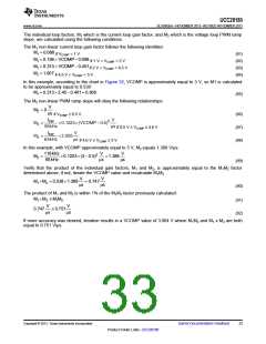
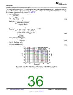
The VCOMP operating point is found on the following chart, M1M2 vs. VCOMP. Once the M1M2 result is
calculated above, find the resultant VCOMP voltage at that operating point to calculate the individual M1 and M2
components.
4.0
3.5
3.0
2.5
2.0
1.5
1.0
0.5
0.0
0.0 0.5 1.0 1.5 2.0 2.5 3.0 3.5 4.0 4.5 5.0
VCOMP (V)
C007
Figure 32. M1M2 vs. VCOMP
For the given M1M2 of 0.751 V/µs, the VCOMP approximately equal to 3 V, as shown in Figure 32.
32
Submit Documentation Feedback
Copyright © 2013, Texas Instruments Incorporated
Product Folder Links :UCC28180

 TI [ TEXAS INSTRUMENTS ]