UCC28180
SLUSBQ5A –NOVEMBER 2013–REVISED NOVEMBER 2013
www.ti.com
The non-linear gain variable, M3, can now be calculated:
M3 = 0
if VCOMP < 5 V
(93)
(94)
(95)
(96)
fSW
65kHz ms
fSW
65kHz ms
fSW
65kHz ms
fSW
65kHz ms
M3 = 0
V
M3 =
M3 =
M3 =
M3 =
´
´(0.0166´ VCOMP - 0.0083)
if 0.5 V < VCOMP < 1 V
V
´
´(0.0572´ VCOMP2 - 0.0597´ VCOMP + 0.0155)
´(0.1148´ VCOMP2 - 0.1746´ VCOMP + 0.0586)
´(0.1148´ VCOMP2 - 0.1746´ VCOMP + 0.0586)
if 1 V < VCOMP < 2 V
if 2 V < VCOMP < 4.5 V
if 4.5 V < VCOMP < 4.6 V
V
´
V
´
(97)
(98)
if 4.6 V < VCOMP < 5 V
In this example, using 3.004 V for VCOMP for a more precise calculation, M3 calculates to 1.035 V/µs:
118kHz
V
V
M3 =
´
65kHz ms
´(0.1148´3.0042 - 0.1746´ 3.004 + 0.0586) = 1.035
ms
(99)
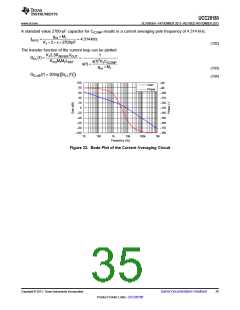
For designs that allow a high inductor ripple current, the current averaging pole, which functions to flatten out the
ripple current on the input of the PWM comparator, should be at least decade before the converter switching
frequency. Analysis on the completed converter may be needed to determine the ideal compensation pole for the
current averaging circuit as too large of a capacitor on ICOMP will add phase lag and increase iTHD where as too
small of an ICOMP capacitor will result in not enough averaging and an unstable current averaging loop. The
frequency of the current averaging pole, fIAVG, is chosen to be at approximately 5 kHz for this design as the
current ripple factor, ∆IRIPPLE, was chosen at the onset of the design process to be 40%, which is large enough to
force DCM operation and result in relatively high inductor ripple current. The required capacitor on ICOMP,
CICOMP, for this is determined using the transconductance gain, gmi, of the internal current amplifier:
g
mi ´M1
CICOMP
=
K12pf
IAVG
(100)
(101)
0.95mS´0.538
7 ´ 2´ p ´3kHz
CICOMP
=
= 2330pF
34
Submit Documentation Feedback
Copyright © 2013, Texas Instruments Incorporated
Product Folder Links :UCC28180

 TI [ TEXAS INSTRUMENTS ]