UCC28180
www.ti.com
SLUSBQ5A –NOVEMBER 2013–REVISED NOVEMBER 2013
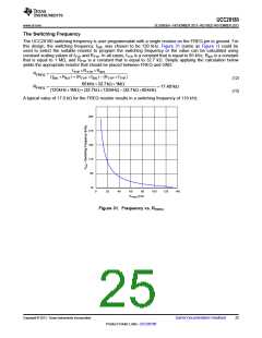
Boost Inductor
Based upon the allowable inductor ripple current discussed above, the boost inductor, LBST, is selected after
determining the maximum inductor peak current, IL_PEAK
:
IRIPPLE
+
IL _ PEAK(max) = I
IN(max)
(26)
(27)
2.575 A
IL _ PEAK(max) = 6.436 A +
= 7.724 A
The minimum value of the boost inductor is calculated based upon the acceptable ripple current, IRIPPLE, at a
worst case duty cycle of 0.5:
VOUTD(1- D)
LBST(min)
³
fSWIRIPPLE
(28)
(29)
390 V ´0.5(1- 0.5)
LBST(min)
³
³ 321mH
The recommended minimum value for the boost inductor assuming a 40% ripple current is 321 µH; the actual
value of the boost inductor that will be used is 327 µH. With this actual value used, the actual resultant inductor
current ripple will be:
LBST = 327mH
(30)
VOUTD(1- D)
IRIPPLE(actual)
=
fSWLBST
(31)
390 V ´0.5(1- 0.5)
118kHz ´327mH
IRIPPLE(actual)
=
= 2.527 A
(32)
(33)
2.527 A
IL _ PEAK(max) = 6.436 A +
= 7.7 A
The duty cycle is a function of the rectified input voltage and will be continuously changing over the half line
cycle. The duty cycle, DUTY(max), can be calculated at the peak of the minimum input voltage:
VOUT - V
=
IN_ RECTIFIED(min)
DUTY
(max)
VOUT
(34)
(35)
V
=
2 ´85 V = 120 V
IN_ RECTIFIED(min)
390 V -120 V
DUTY
=
= 0.692
(max)
390 V
(36)
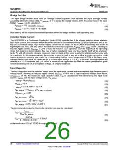
Boost Diode
The diode losses are estimated based upon the forward voltage drop, VF, at 125°C and the reverse recovery
charge, QRR, of the diode. Using a silicon carbide Schottky diode, although more expensive, will essentially
eliminate the reverse recovery losses and result in less power dissipation:
PDIODE = VF _125CIOUT(max) + 0.5fSW VOUTQRR
(37)
(38)
(39)
VF _125°C = 1V
QRR = 0nC
PDIODE = 1V ´0.923 A + 0.5 ´119kHz ´390 V ´0nC = 0.923W
)
(
) (
(40)
This output diode should have a blocking voltage that exceeds the output over voltage of the converter and be
attached to an appropriately sized heat sink.
Copyright © 2013, Texas Instruments Incorporated
Submit Documentation Feedback
27
Product Folder Links :UCC28180

 TI [ TEXAS INSTRUMENTS ]