ꢀꢁꢁ ꢂ ꢃꢄ ꢅ ꢆꢇ ꢈ ꢆꢄ ꢈꢆꢂ ꢈ ꢆꢅ ꢈꢆ ꢉꢈ ꢆ ꢊꢆ ꢋ ꢄ
ꢌ ꢍ ꢎꢆꢏꢍ ꢎ ꢐꢑ ꢒꢓ ꢁꢔꢍ ꢕ ꢁꢀꢑ ꢑꢐꢖꢗꢆꢔꢍ ꢘ ꢐ ꢏ ꢎꢔ
ꢙ
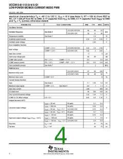
SGLS245 − MAY 2004
electrical characteristics T = −40_C to 125_C, V
= 10 V (see Note 1), RT = 100 kΩ from REF to
A
CC
RC, CT = 330 pF from RC to GND, 0.1 F capacitor from V
to GND, 0.1 F capacitor from V
to GND
CC
REF
and T = T (unless otherwise stated)
A
J
PARAMETER
TEST CONDITIONS
MIN
TYP
MAX
UNITS
Undervoltage Lockout Section
UCC2813-0
6.6
7.2
7.8
10.2
13.5
4.5
7.5
8
UCC2813-1
UCC2813-2/4
UCC2813-3/5
UCC2813-0
UCC2813-1
UCC2813-2/4
UCC2813-3/5
UCC2813-0
UCC2813-1
UCC2813-2/4
UCC2813-3/5
8.6
11.5
3.7
9.4
12.5
4.1
6.9
7.4
8.3
3.6
0.3
2
Start threshold
See Note 6
See Note 6
V
V
6.3
6.8
Stop threshold
7.6
9
3.2
4
0.12
1.6
0.48
2.4
5.1
0.8
Start to stop hysteresis
V
3.5
4.2
0.5
0.2
Soft Start Section
COMP rise time
FB = 1.8 V,
Rise from 0.5 V to REF − 1 V
4
10
ms
Overall Section
Start-up current
V
< Start Threshold
0.1
0.5
0.23
1.2
15
mA
mA
V
CC
FB = 0 V,
= 10 mA,
Operating supply current
CS = 0 V,
RC = 0 V
V
V
internal zener voltage
I
See Notes 6 and 8
12
13.5
CC
CC
internal zener voltage minus start
CC
See Note 6
UCC2813-2/4
0.5
1.0
V
threshold voltage
NOTES: 1. Adjust V
above the start threshold before setting at 10 V.
CC
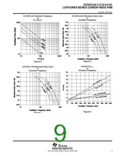
2. Oscillator frequency for the UCC2813-0, UCC2813-2, and UCC2813-3 is the output frequency.
Oscillator frequency for the UCC2813-1, UCC2813-4, and UCC2813-5 is twice the output frequency.
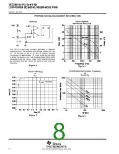
3. Gain is defined by:
0 v V
v 0.8 V.
DV
CS
COMP
A =
DV
CS
4. Parameter measured at trip point of latch with pin 2 at 0 V.
5. Total variation includes temperature stability and load regulation.
6. Start threshold, stop threshold, and Zener shunt thresholds track one another.
7. Not production tested.
8. The device is fully operating in clamp mode as the forcing current is higher than the normal operating supply current.
5
POST OFFICE BOX 655303 • DALLAS, TEXAS 75265

 TI [ TEXAS INSTRUMENTS ]