UC2906
UC3906
OPERATION AND APPLICATION INFORMATION (continued)
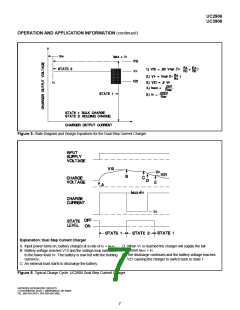
Figure 5. State Diagram and Design Equations for the Dual Step Current Charger
Explanation: Dual Step Current Charger
A. Input power turns on, battery charges at a rate of IH + IMAX.
B. Battery voltage reaches V12 and the voltage loop switches
to the lower level VF. The battery is now fed with the holding
current IH.
D. When VF is reached the charger will supply the full
current IMAX + IH.
E. The discharge continues and the battery voltage reaches
V21 causing the charger to switch back to state 1.
C. An external load starts to discharge the battery.
Figure 6. Typical Charge Cycle: UC2906 Dual Step Current Charger
UNITRODE INTEGRATED CIRCUITS
7 CONTINENTAL BLVD. • MERRIMACK, NH 03054
TEL. 603-424-2410 • FAX 603-424-3460
7

 TI [ TEXAS INSTRUMENTS ]