UC2906
UC3906
OPERATION AND APPLICATION INFORMATION (continued)
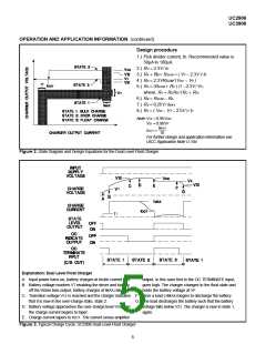
Design procedure
1.) Pick divider current, ID. Recommended value is
50µA to 100µA.
2.) RC = 2.3V ⁄ ID
3.) RA + RB = RSUM = ( VF − 2.3V )⁄ ID
4.) RD = 2.3VRSUM⁄ (VOC − VF )
5.) RA = (RSUM + RX ) (1 −2.3V ⁄ VT)
where: RX = RCRD ⁄ (RC + RD)
6.) RB = RSUM − RA
7.) RS = 0.25V ⁄ IMAX
8.) RT = ( VIN − VT − 2.5V ) ⁄ IT
Note:V12 = 0.95VOC
V31 = 0.90VF
IMAX
IOCT =
10
For further design and application information see
UICC Application Note U-104
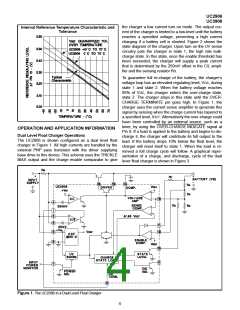
Figure 2. State Diagram and Design Equations for the Dual Level Float Charger
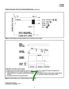
Explanation: Dual Level Float Charger
A. Input power turns on, battery charges at trickle current rate.
B. Battery voltage reaches VT enabling the driver and turning
off the trickle bias output, battery charges at lMAX rate.
output, in this case tied to the OC TERMINATE input,
goes high. The charger changes to the float state and
holds the battery voltage at VF.
C. Transition voltage V12 is reached and the charger indicates F. Here a load (>lMAX) begins to discharge the battery.
that it is now in the over-charge state, state 2.
D. Battery voltage approaches the over-charge level VOC and
the charge current begins to taper.
G. The load discharges the battery such that the battery
voltage falls below V31. The charger is now in state 1,
again.
E. Charge current tapers to lOCT. The current sense amplifier
Figure 3. Typical Charge Cycle: UC2906 Dual Level Float Charger
5

 TI [ TEXAS INSTRUMENTS ]