UC2906
UC3906
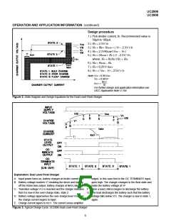
OPERATION AND APPLICATION INFORMATION (continued)
Compensated Reference Matches Battery Requirements
at the current sense output to prevent excessive power
dissipation on the UC2906.
When the charger is in the float state, the battery will be
maintained at a precise float voltage, VF. The accuracy of
this float state will maximize the standby life of the battery
while the bulk-charge and over-charge states guarantee
rapid and full re-charge. All of the voltage thresholds on
the UC2906 are derived from the internal reference. This
reference has a temperature coefficient that tracks the
temperature characteristic of the optimum-charge and
hold levels for sealed lead-acid cells. This further guaran-
tees that proper charging occurs, even at temperature ex-
tremes.
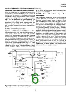
A PNP Pass Device Reduces Minimum Input to Out-
put Differential
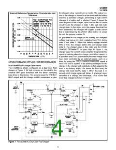
The configuration of the driver on the UC2906 allows a
good bit of flexibility when interfacing to an external pass
transistor. The two chargers shown in Figures 1 and 4
both use PNP pass devices, although an NPN device
driven from the source output of the UC2906 driver can
also be used. In situations where the charger must oper-
ate with low input to output differentials the PNP pass de-
vice should be configured as shown in Figure 4. The PNP
can be operated in a saturated mode with only the series
diode and sense resistor adding to the minimum differen-
tial. The series diode, D1, in many applications, can be
eliminated. This diode prevents any discharging of the
battery, except through the sensing divider, when the
charger is attached to the battery with no input supply
voltage. If discharging under this condition must be kept
to an absolute minimum, the sense divider can be refer-
enced to the POWER INDICATE pin, Pin 7, instead of
ground. In this manner the open collector off state of Pin
7 will prevent the divider resistors from discharging the
battery when the input supply is removed.
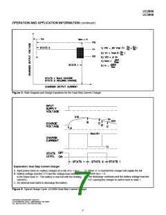
Dual Step Current Charger Operation
Figures 4, 5 and 6 illustrate the UC2906’s use in a differ-
ent charging scheme. The dual step current charger is
useful when a large string of series cells must be
charged. The holding-charge state maintains a slightly
elevated voltage across the batteries with the holding cur-
rent, 1H. This will tend to guarantee equal charge distribu-
tion between the cells. The bulk-charge state is similar to
that of the float charger with the exception that when V12
is reached, no over-charge state occurs since Pin 8 is tied
high at all times. The current sense amplifier is used to
regulate the holding current. In some applications a series
resistor, or external buffering transistor, may be required
Figure 4. The UC2906 in a Dual Step Current Charger
6

 TI [ TEXAS INSTRUMENTS ]