UC2625-EP
SLUS802–MARCH 2008 .................................................................................................................................................................................................. www.ti.com
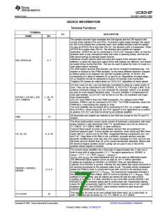
Terminal Functions (continued)
TERMINAL
I/O
DESCRIPTION
NAME
NO.
These outputs can drive the gates of N-channel power MOSFETs directly or they
can drive the bases of power Darlingtons if some form of current limiting is used.
They are meant to drive low-side power devices in high-current output stages.
Current available from these pins can peak as high as 0.5 A. These outputs feature
a true totem-pole output stage. Beware of exceeding device power dissipation
limits when using these outputs for high continuous currents. These outputs pull
high to turn a “low-side” device on (active high).
PDA, PDB, PDC
12, 13, 14
These outputs are open-collector, high-voltage drivers that are meant to drive
high-side power devices in high-current output stages. These are active low
outputs, meaning that these outputs pull low to command a high-side device on.
These outputs can drive low-voltage PNP Darlingtons and P-channel MOSFETs
directly, and can drive any high-voltage device using external charge pump
techniques, transformer signal coupling, cascode level-shift transistors, or
opto-isolated drive (high-speed opto devices are recommended). (See
applications).
PUA, PUB, PUC
PWR VCC
16, 17, 18
This supply pin carries the current sourced by the PD outputs. When connecting
PD outputs directly to the bases of power Darlingtons, the PWR VCC pin can be
current limited with a resistor. Darlington outputs can also be "Baker Clamped" with
diodes from collectors back to PWR VCC. (See Applications)
11
The device can chop power devices in either of two modes, referred to as
“two-quadrant” (Quad Sellow) and “four quadrant” (Quad Sel high). When
two-quadrant chopping, the pulldown power devices are chopped by the output of
the PWM latch while the pullup drivers remain on. The load chops into one
commutation diode, and except for back-EMF, will exhibit slow discharge current
and faster charge current. Two-quadrant chopping can be more efficient than
four-quadrant.
QUAD SEL
22
When four-quadrant chopping, all power drivers are chopped by the PWM latch,
causing the load current to flow into two diodes during chopping. This mode
exhibits better control of load current when current is low, and is preferred in servo
systems for equal control over acceleration and deceleration. The QUAD SEL input
has no effect on operation during braking.
Each time the TACH-OUT pulses, the capacitor tied to RC-BRAKE discharges
from approximately 3.33 V down to 1.67 V through a resistor. The tachometer
pulse width is approximately T = 0.67 RT CT, where RT and CT are a resistor and
capacitor from RC-BRAKE to ground. Recommended values for RT are 10 kΩ to
500 kΩ, and recommended values for CT are 1 nF to 100 nF, allowing times
between 5 µs and 10 ms. Best accuracy and stability are achieved with values in
the centers of those ranges.
RC-BRAKE also has another function. If RC-BRAKE pin is pulled below the brake
threshold, the device enters brake mode. This mode consists of turning off all three
high-side devices, enabling all three low-side devices, and disabling the
tachometer. The only things that inhibit low-side device operation in braking are
low-supply, exceeding peak current, OV-COAST command, and the PWM
comparator signal. The last of these means that if current sense is implemented
such that the signal in the current sense amplifier is proportional to braking current,
the low-side devices will brake the motor with current control. (See applications)
Simpler current sense connections results in uncontrolled braking and potential
damage to the power devices.
RC-BRAKE
21
The UC3625 can regulate motor current using fixed-frequency pulse width
modulation (PWM). The RC-OSC pin sets oscillator frequency by means of timing
resistor ROSC from the RC-OSC pin to VREF and capacitor COSC from RC-OSC
to Gnd. Resistors 10 kΩ to 100 kΩ and capacitors 1 nF to 100 nF works the best,
but frequency should always be below 500 kHz. Oscillator frequency is
approximately:
RC-OSC
25
F = 2/(ROSC x COSC )
Additional components can be added to this device to cause it to operate as a
fixed off-time PWM rather than a fixed frequency PWM, using the RC-OSC pin to
select the monostable time constant.
The voltage on the RC-OSC pin is normally a ramp of about 1.2 V peak-to-peak,
centered at approximately 1.6 V. This ramp can be used for voltage-mode PWM
control, or can be used for slope compensation in current-mode control.
8
Submit Documentation Feedback
Copyright © 2008, Texas Instruments Incorporated
Product Folder Link(s) :UC2625-EP

 TI [ TEXAS INSTRUMENTS ]