UC2625-EP
www.ti.com .................................................................................................................................................................................................. SLUS802–MARCH 2008
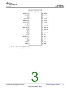
DEVICE INFORMATION
Terminal Functions
TERMINAL
I/O
DESCRIPTION
NAME
NO.
The position decoder logic translates the Hall signals and the DIR signal to the
correct driver signals (PUs and PDs). To prevent output stage damage, the signal
on DIR is first loaded into a direction latch, then shifted through a two-bit register.
As long as SPEED-IN is less than 250 mV, the direction latch is transparent. When
SPEED-IN is higher than 250 mV, the direction latch inhibits all changes
indirection. SPEED-IN can be connected to TACH-OUT through a filter, so that the
direction latch is only transparent when the motor is spinning slowly, and has too
little stored energy to damage power devices.
Additional circuitry detects when the input and output of the direction latch are
different, or when the input and output of the shift register are different, and inhibits
all output drives during that time. This can be used to allow the motor to coast to a
safe speed before reversing.
DIR, SPEED-IN
6, 7
The shift register ensures that direction can not be changed instantaneously. The
register is clocked by the PWM oscillator, so the delay between direction changes
is always going to be between one and two oscillator periods. At 40 kHz, this
corresponds to a delay of between 25 µs and 50 µs. Regardless of output stage,
25 µs deadtime should be adequate to ensure no overlap cross-conduction.
Toggling DIR causes an output pulse on TACH-OUT regardless of motor speed.
E/A IN(+) and E/A IN(–) are not internally committed to allow for a wide variety of
uses. They can be connected to the ISENSE, to TACH-OUT through a filter, to an
external command voltage, to a D/A converter for computer control, or to another
op amp for more elegant feedback loops. The error amplifier is compensated for
unity gain stability, so E/A OUT can be tied to E/A IN(–) for feedback and major
loop compensation.
E/A OUT and PWM In drive the PWM comparator. For voltage-mode PWM
systems, PWM In can be connected to RC-OSC. The PWM comparator clears the
PWM latch, commanding the outputs to chop.
E/A IN(+), E/A IN(–), E/A
OUT, PWM IN
1, 28, 27,
26
The error amplifier can be biased off by connecting E/A IN(–) to a higher voltage
than /EA IN(+). When biased off, E/A OUT appears to the application as a resistor
to ground. E/A OUT can then be driven by an external amplifier.
All thresholds and outputs are referred to the GND pin except for the PD and PU
outputs.
GND
15
The three shaft position sensor inputs consist of hysteresis comparators with input
pullup resistors. Logic thresholds meet TTL specifications and can be driven by
5-V CMOS, 12-V CMOS, NMOS, or open-collectors.
Connect these inputs to motor shaft position sensors that are positioned 120
electrical degrees apart. If noisy signals are expected, zener clamp and filter these
inputs with 6-V zeners and an RC filter. Suggested filtering components are 1 kΩ
and 2 nF. Edge skew in the filter is not a problem, because sensors normally
generate modified gray code with only one output changing at a time, but rise and
fall times must be shorter than 20 µs for correct tachometer operation. Motors with
60 electrical degree position sensor coding can be used if one or two of the
position sensor signals is inverted.
H1, H2, H3
8, 9, 10
The current sense amplifier has a fixed gain of approximately two. It also has a
built-in level shift of approximately 2.5 V. The signal appearing on ISENSE is:
ISENSE = 2.5 V + (2 × ABS ( ISENSE1 – ISENSE2) )
ISENSE1 and ISENSE2 are interchangeable and can be used as differential inputs.
The differential signal applied can be as high as ±0.5 V before saturation.
If spikes are expected on ISENSE1 or ISENSE2, they are best filtered by a
capacitor from ISENSE to ground. Filtering this way allows fast signal inversions to
be correctly processed by the absolute value circuit. The peak-current comparator
allows the PWM to enter a current-limit mode with current in the windings never
exceeding approximately 0.2 V / RSENSE. The overcurrent comparator provides a
fail-safe shutdown in the unlikely case of current exceeding 0.3 V / RSENSE. Then,
softstart is commanded, and all outputs are turned off until the high current
condition is removed. It is often essential to use some filter driving ISENSE1 and
ISENSE2 to reject extreme spikes and to control slew rate. Reasonable starting
values for filter components might be 250-Ω series resistors and a 5-nF capacitor
between ISENSE1 and ISENSE2. Input resistors should be kept small and
matched to maintain gain accuracy.
ISENSE1, ISENSE2,
ISENSE
3, 4, 5
This input can be used as an over-voltage shut-down input, as a coast input, or
both. This input can be driven by TTL, 5-V CMOS, or 12-V CMOS.
OV-COAST
23
Copyright © 2008, Texas Instruments Incorporated
Submit Documentation Feedback
7
Product Folder Link(s) :UC2625-EP

 TI [ TEXAS INSTRUMENTS ]