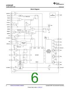
UC2625-EP
www.ti.com .................................................................................................................................................................................................. SLUS802–MARCH 2008
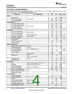
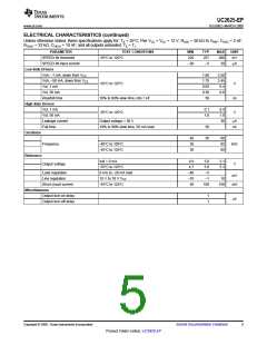
ELECTRICAL CHARACTERISTICS (continued)
Unless otherwise stated, these specifications apply for: TA = 25°C; Pwr VCC = VCC = 12 V; ROSC = 20 kΩ to VREF; COSC = 2 nF;
RTACH = 33 kΩ; CTACH = 10 nF; and all outputs unloaded. TA = TJ.
PARAMETER
TEST CONDITIONS
-55°C to 125°C
MIN
220
–30
TYP
257
–5
MAX
290
30
UNIT
mV
SPEED-IN threshold
SPEED-IN input current
µA
Low-Side Drivers
Voh, –1 mA, down from VCC
Voh, –50 mA, down from VCC
Vol, 1 mA
1.60
1.75
0.05
0.36
50
2.50
2.45
0.4
-55°C to 125°C
V
ns
V
Vol, 50 mA
0.8
Rise/fall time
10% to 90% slew time, into 1 nF
-55°C to 125°C
High-Side Drivers
Vol, 1 mA
0.1
1.0
0.4
1.8
30
Vol, 50 mA
Leakage current
Fall time
Output voltage = 50 V
µA
10% to 90% slew time, 50 mA load
50
50
ns
Oscillator
Reference
40
35
30
60
65
80
Frequency
-40°C to 105°C
-55°C to 125°C
kHz
Iref = 0 mA
4.9
4.7
–40
–10
50
5.0
5.0
–5
5.1
5.3
Output voltage
V
-55°C to 125°C
0 mA to –20 mA load
10 V to 18 V VCC
-55°C to 125°C
Load regulation
Line regulation
mV
mA
–1
10
Short circuit current
100
150
Miscellaneous
Output turn-on delay
1
1
µs
Output turn-off delay
Copyright © 2008, Texas Instruments Incorporated
Submit Documentation Feedback
5
Product Folder Link(s) :UC2625-EP

 TI [ TEXAS INSTRUMENTS ]