TPS929160-Q1
ZHCSNG0 – APRIL 2023
www.ti.com.cn
7.3.7.9 LED Short-Circuit Diagnostics in NORMAL state
The TPS929160-Q1 has internal analog comparators to monitor all channel outputs with respect to a fixed
threshold for reporting OUTXn short to GND fault.
The short-circuit detection is only effective during PWM-ON state with programmable minimal pulse width of
t(BLANK) + t(SHORT_deg). The t(BLANK) is programmable by register BLANK. If PWM on-time is less than t(BLANK)
t(SHORT_deg), the device can not report any short-circuit fault.
+
When the voltage V(OUTXn) is below threshold V(SG_th_rising) with duration longer than deglitch timer length of
t(BLANK) + t(SHORT_deg), the device pulls the ERR pin down with pulsed current sink for 50 µs to report fault and set
flag registers including FLAG_SHORTOUTXn, FLAG_OUT and FLAG_ERR. In NORMAL state, the device does
not take any actions in response the LED short-circuit fault and waits for the master controller to determine the
protection behavior.
The fault is latched in flag registers. When the voltage V(OUTXn) rises above threshold V(SG_th_falling) with duration
longer than deglitch timer length of t(BLANK) + t(SHORT_deg), the master controller must write 1 to CLRFAULT to
clear FLAG_SHORTOUTXn, FLAG_OUT and FLAG_ERR. The CLRFAULT bit automatically returns to 0.
7.3.7.10 Single-LED Short-Circuit Detection in NORMAL state
The TPS929160-Q1 also integrates analog comparators to monitor all outputs with respect to two alternative
threshold for single-LED short-circuit diagnostic. Setting the register SLSEN to 1 enables the single-LED short-
circuit detection.
The single-LED, short-circuit detection is only effective during PWM-ON state with programmable minimal pulse
width of t(BLANK) + t(SLS_deg). The t(BLANK) is programmable by register BLANK. If PWM on-time is less than
t(BLANK) + t(SLS_deg), the device cannot report any single-LED short-circuit fault. When the device supply voltage
V(SUPPLY) is below the threshold V(LOWSUPTH) set by register LOWSUPTH, the single-LED short-circuit is not
detected nor reported.
When the voltage V(OUTXn) is below threshold V(SLSTHx) with duration longer than deglitch timer length of
t(BLANK) + t(SLS_deg), and the device supply voltage V(SUPPLY) is above the threshold V(LOWSUPTH) set by register
LOWSUPTH, the device pulls the ERR pin down with pulsed current sink for 50 µs to report fault and set
flag registers including FLAG_SLSOUTXn, FLAG_OUT and FLAG_ERR. The TPS929160-Q1 provides two
alternative thresholds V(SLSTH0) and V(SLSTH1) for single-LED short-circuit detection selected by SLSTHOUTXn
independently for each current output. The V(SLSTH0) is selected for current OUTXn when SLSTHOUTXn is set
to 0, however V(SLSTH1) is selected when SLSLTHOUTXn is set to 1. The actual voltage value for V(SLSTH0)
and V(SLSTH1) is programmable by two 8-bit registers SLSTH0 and SLSTH1 from 2.5 V to 34.375 V at 125-mV
interval. In NORMAL state, the device does not take any actions in response the single-LED short-circuit fault
and waits for the master controller to determine the protection behavior.
The fault is latched in flag registers. When the voltage V(OUTXn) rises above threshold V(SLSTHx) + 275 mV with
duration longer than deglitch timer length of t(BLANK) + t(SLS_deg), or the device supply voltage V(SUPPLY) is below
the threshold V(LOWSUPTH), the master controller must write 1 to register CLRFAULT to clear FLAG_SLSOUTXn,
FLAG_OUT and FLAG_ERR. The CLRFAULT automatically returns to 0.
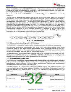
7.3.7.11 EEPROM CRC Error in NORMAL state
The TPS929160-Q1 implements a EEPROM CRC check after loading the EEPROM code to configuration
register in NORMAL state.
The calculated CRC result is sent to register CALC_EEPCRC and compared to the data in register EEPCRC,
which stores the CRC code for all EEPROM registers except for DIM-R reserved register. The reserved DIM-R
register value is not included in the EEPCRC calculation. The TPS929160-Q1 EEPROM configuration tool are
available on ti.com to help calculate the EEPCRC value. If the code in register CALC_EEPCRC is not matched
to the code in register EEPCRC, the TPS929160-Q1 pulls the ERR pin down with pulsed current sink for 50
µs to report the fault and set the registers including FLAG_EEPCRC and FLAG_ERR to 1. The TPS929160-Q1
only loads EEPROM to corresponding registers one time during initialization state. Parity check is used to detect
whether the internal configuration parameters are correctly loaded from trim EEPROM or not. When there is
Copyright © 2023 Texas Instruments Incorporated
Submit Document Feedback
31
Product Folder Links: TPS929160-Q1
English Data Sheet: SLVSG60

 TI [ TEXAS INSTRUMENTS ]