TPS929160-Q1
www.ti.com.cn
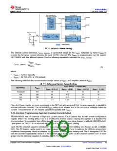
D(OUTXn)
where
ZHCSNG0 – APRIL 2023
PWMOUTXn
256
=
ì100%
(5)
•
•
PWMOUTXn is decimal number from 0 to 255.
X is from A to H, n is 0 or 1 for different output channel.
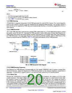
7.3.3.6 Exponential Brightness Control
The TPS929160-Q1 can also generate PWM duty-cycle output following exponential curve. EXPEN bit selects
the dimming method between linear or exponential. When register EXPEN is set to 1, the integrated look-
up table provides a one-to-one conversion from 8-bit register PWMOUTXn to 12-bit binary code following
exponential increment, as the following figure illustrates. When exponential control path is selected, the
PWMLOWOUTXn data is neglected. By using the exponential brightness control, LED brightness change by
one LSB is invisible to human eyes especially at low brightness range.
4096
3584
3072
2560
2048
1536
1024
512
0
0
32
64
96
128
160
192
224
256
8-Bit PWMOUTXn[7:0]
图 7-5. PWM Duty Cycle vs 8-Bit Code for Exponential Dimming
During power up or in FAIL-SAFE state, the registers EXPEN, and PWMFREQ are automatically reset to their
default values stored in their corresponding EEPROM. Both PWMOUTXn and PWMLOWOUTXn are reset to
00h during power up, but load their EEPROM content in FAIL-SAFE state.
7.3.4 FAIL-SAFE State Operation
The TPS929160-Q1 supports independent channel brightness control through the FlexWire interface. The
brightness of each channel is adjustable according to its DC current register IOUTXn, PWM duty cycle register
PWMOUTXn/PWMLOWOUTXn and channel enable register ENOUTXn setting. The brightness of each channel
reflects to its register setting value immediately after register is successfully updated through the FlexWire
interface by master unit. However, the master unit loses the control for all current channels if the FlexWire
communication fails between master unit and the TPS929160-Q1. For example, the interface cable is broken
by accident. As a consequence, the brightness for all output channels of the TPS929160-Q1 are stuck and the
ON and OFF control for all output channels are missed too. To keep the basic ON and OFF control for each
output channels, the TPS929160-Q1 provides a FAIL-SAFE state when the communication to master is lost. For
detailed description for FAIL-SAFE state entering and quitting criteria, refer to Device Functional Modes.
When the TPS929160-Q1 is entering FAIL-SAFE state, all the registers are set to default value or reloaded from
EEPROM including IOUTXn, PWMOUTXn, PWMLOWOUTXn and ENOUTXn. The pre-programmed settings in
the EEPROM are loaded and the corresponding registers are reset to the default values. The TPS929160-Q1
provides two hardware input pins, FS0 and FS1 to turn on or off corresponding current output channels in
FAIL-SAFE state. Each current output channel has its own register, FSOUTXn to set the mapping to FS0 or
FS1. When FSOUTXn is set to 0, the corresponding current output channel is controlled by FS0 input, otherwise
it is controlled by FS1 input. If the voltage of FSx input is higher than its high threshold, VIH(IO), all current
Copyright © 2023 Texas Instruments Incorporated
Submit Document Feedback
23
Product Folder Links: TPS929160-Q1
English Data Sheet: SLVSG60

 TI [ TEXAS INSTRUMENTS ]