TPS929160-Q1
ZHCSNG0 – APRIL 2023
www.ti.com.cn
IOUTXn +1
64
I(OUTXn)
=
ìI(FULL _RANGE)
(2)
where
•
•
•
IOUTXn is programmable from 0 to 63.
X is from A to H, n is 0 or 1 for different output channel.
Use 方程式 1 to calculate I(FULL_RANGE)
.
7.3.3 PWM Dimming
TPS929160-Q1 integrates independent 12-bit PWM generators for each OUTXn channel. The current output for
each OUTXn channel is turned on and off controlled by the integrated PWM generator. The average current of
each OUTXn can be adjusted by PWM duty cycle independently, therefore, to control the brightness for LEDs in
each channel.
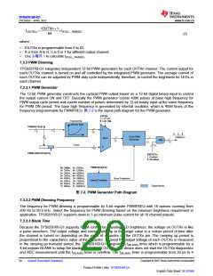
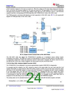
7.3.3.1 PWM Generator
The 12-bit PWM generator constructs the cyclical PWM output based on a 12-bit digital binary input to control
the output current ON and OFF. Basically the PWM generator counts 4096 pulses at base high frequency for
PWM output cycle period and counts number of pulses determined by 12-bit binary input at the same frequency
for PWM ON period. The base high frequency is generated by internal oscillator, which is 4096 times of the
frequency programmable by PWMFREQ. 图 7-2 is the signal path diagram for the PWM generator.
EXPEN
1: LUT EN
0: LUT DIS
Exponential
Look-Up Table
PWMOUTXn[7:0]
1
8
8
12
12-bit PWM
Generator
PWMOUT
MUX
0
8
AND
12
12
12
Linear
12
12
PWMLOWOUTXn[3:0]
ENOUTXn
1: Enabled
0: Disabled
PWMFREQ[3:0]
0h: 200Hz 8h: 1000Hz
1h: 250Hz 9h: 1200Hz
2h: 300Hz Ah: 2000Hz
3h: 350Hz Bh: 4000Hz
4h: 400Hz Ch: 5900Hz
5h: 500Hz Dh: 7800Hz
6h: 600Hz Eh: 9600Hz
7h: 800Hz Fh: 20800Hz
Base Frequency
Internal Oscillator
Digital blocks
图 7-2. PWM Generator Path Diagram
7.3.3.2 PWM Dimming Frequency
The frequency for PWM dimming is programmable by 4-bit register PWMFREQ with 16 options covering from
200 Hz to 20.8 kHz. Select the frequency for PWM dimming based on the minimum brightness requirement in
application. TPS929160-Q1 supports down to 1-µs minimum pulse current for all 16 channel outputs.
7.3.3.3 Blank Time
Because the TPS929160-Q1 supports PWM control for adjusting LED brightness, the voltage on OUTXn is like
a pulse waveform. The output voltage and current ramp up to the target value in a certain period of time after
the channel is turned on depending on the value of capacitor on the OUTXn pin. The ramping up period is
proportional to the capacitance value of the capacitor. To avoid the output voltage of each OUTXn is measured
in the ramping up transient period, the TPS929160-Q1 integrates a t(BLANK) timer which is programmable by a
4-bit register BLANK to setup the blanking time for all OUTXn. The device does not start the OUTXn diagnostics
and ADC measurement until the t(BLANK) timer is overflow. The t(BLANK) timer is programmable from 20 μs to 4
Copyright © 2023 Texas Instruments Incorporated
20
Submit Document Feedback
Product Folder Links: TPS929160-Q1
English Data Sheet: SLVSG60

 TI [ TEXAS INSTRUMENTS ]