TPS929160-Q1
ZHCSNG0 – APRIL 2023
www.ti.com.cn
7.3.1.4 Undervoltage Lockout (UVLO) and Power-On-Reset (POR)
To ensure clean start-up, the TPS929160-Q1 uses UVLO and POR circuitry to clear its internal registers upon
power up and to reset registers with its default values.
The TPS929160-Q1 has internal UVLO circuits so that when either input voltage V(VBAT) or LDO output voltage
V(LDO) is lower than its UVLO threshold, POR is triggered. In POR state, the device resets digital core and all
registers to default value. FLAG_POR and FLAG_ERR register are set to 1 for each POR cycle to indicate the
POR history.
Before both powers are above UVLO thresholds, the TPS929160-Q1 stays in POR state with all outputs off
and ERR pulled down. Once both power supplies are above UVLO threshold, the device enters INIT mode for
initialization releasing ERR pulldown. A programmable timer starts counting in INIT state, the timer length can
be set by EEPROM register INITTIMER. When the timer is completed, the device switches to NORMAL state. In
INIT state, setting CLRPOR to 1 clears FLAG_POR, disables the timer, and sets the device to NORMAL state.
Upon powering up, the TPS929160-Q1 automatically loads all settings stored in EEPROM to correlated registers
and sets the other registers to default value which don't have correlated EEPROM. All channels are powered up
in OFF state by default to avoid unwanted blinking.
Writing 1 to REGDEFAULT manually loads EEPROM setting to the correlated registers and set the other
registers to default value. After REGDEFAULT is set, the FLAG_POR is cleared to 0. Writing 1 to CLRPOR also
resets the FLAG_POR register to 0. TI recommends setting REGDEFAULT to 1 to clear the internal registers
every time after POR. The REGDEFAULT automatically resets to 0.
7.3.1.5 Power Supply (SUPPLY)
The TPS929160-Q1 has two additional SUPPLY input pins for powering all 16 high-side current output channels.
The supply voltage input to the device through two SUPPLY pin can be low to 3.5 V and up to 36 V for either
automotive battery directly powered systems or an external DC to DC converter output. An external DC to DC
converter can provide a regulated voltage for required LED output forward voltage from wide automotive battery
voltage range.
The TPS929160-Q1 has an internal undervoltage detection circuit for SUPPLY input. When the SUPPLY input
voltage is lower than its undervoltage threshold, V(SUPUV_th_falling), all 16 current output channels are disabled
with ERR pin constantly pulled low and register flags set to 1 including FLAG_ERR bit and FLAG_SUPUV bit. 表
7-6 shows the detailed fault behavior in NORMAL state.
7.3.1.6 Programmable Low Supply Warning
The TPS929160-Q1 uses its internal comparator to monitor supply voltage V(SUPPLY). If the supply is below
allowable working threshold, the output voltage can be insufficient to keep the LED operating with desired
brightness output as expected. The supply voltage is automatically compared with threshold set by register
LOWSUPTH. When the supply voltage is below threshold, the device sets warning flag register FLAG_LOWSUP
and FLAG_ERR to 1 in the status register. CLRFAULT is able to clear the FLAG_LOWSUP as well as other fault
registers. Low-supply warning will clear LED open and single-LED short fault. In addition, the LED open-circuit
and single LED short-circuit detection is disabled if the supply voltage is below threshold to avoid LED open
circuit and to prevent the single LED short-circuit fault from being mis-triggered. The 5-bit register LOWSUPTH
has a total of 32 options covering from 4 V to 35 V at 1-V interval.
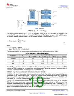
7.3.2 Constant Current Output
7.3.2.1 Reference Current with External Resistor (REF)
The TPS929160-Q1 must have an external resistor R(REF) to set the internal current reference I(REF) as shown in
图 7-1.
Copyright © 2023 Texas Instruments Incorporated
English Data Sheet: SLVSG60
18
Submit Document Feedback
Product Folder Links: TPS929160-Q1

 TI [ TEXAS INSTRUMENTS ]