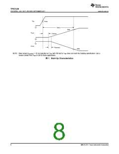
TPS7A39
www.ti.com.cn
ZHCSGP0A –JULY 2017–REVISED SEPTEMBER 2017
6.3 Recommended Operating Conditions
over operating free-air temperature range (unless otherwise noted)
MIN
3.3
NOM
MAX
33
UNIT
V
|VINx
|
Supply voltage magnitude for either regulator
Enable supply voltage
VEN
0
VINP
30
V
VOUTP
VOUTN
IOUTx
IBUF
Positive regulated output voltage range
Negative regulated output voltage range
Output current for either regulator
VFBP
–30
0.005(1)
0
V
VFBN
150
1000
V
mA
µA
µF
µF
nF
nF
nF
kΩ
kΩ
°C
Output current from the BUF pin
120
10(2)
10(2)
10
CINx
Input capacitor for either regulator
4.7
COUTx
CNR/SS
CFFP
CFFN
R2P
Output capacitor for either regulator
4.7
0(3)
Noise-reduction and soft-start capacitor
Positive channel feed-forward capacitor; connect from VOUTP to FBP
Negative channel feed-forward capacitor; connect from VOUTN to FBN
Lower positive feedback resistor
1000
100
100
240
240
125
0
10
0
10
10
R2N
Lower negative feedback resistor (from FBN to BUF)
Operating junction temperature
10
TJ
–40
(1) Minimum load required when feedback resistors are not used. If feedback resistors are used, keeping R2x below 240 kΩ satisfies this
requirement.
(2) The nominal input and output capacitor value of 10-µF accounts for the derating factors that apply to X5R and X7R ceramic capacitors.
The assumed overall derating is 80%.
(3) For startup tracking to function correctly a minimum 4.7-nF CNR/SS capacitor must be used.
6.4 Thermal Information
TPS7A39
THERMAL METRIC(1)
DSC (WSON)
10 PINS
44.4
UNIT
RθJA
Junction-to-ambient thermal resistance
°C/W
°C/W
°C/W
°C/W
°C/W
°C/W
RθJC(top)
RθJB
Junction-to-case(top) thermal resistance
Junction-to-board thermal resistance
33.7
19.4
ψJT
Junction-to-top characterization parameter
Junction-to-board characterization parameter
Junction-to-case(bottom) thermal resistance
0.4
ψJB
19.5
RθJC(bot)
2.9
(1) For more information about traditional and new thermal metrics, see the Semiconductor and IC Package Thermal Metrics application
report.
Copyright © 2017, Texas Instruments Incorporated
5

 TI [ TEXAS INSTRUMENTS ]