TPS74801-Q1
SLVSAI4A –OCTOBER 2010–REVISED FEBRUARY 2011
www.ti.com
DROPOUT VOLTAGE
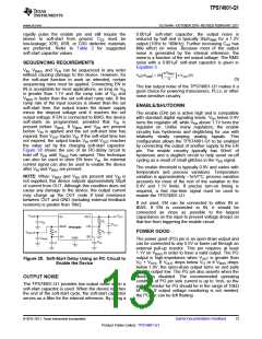
The second specification (shown in Figure 27) is
referred to as VBIAS Dropout and applies to
applications where IN and BIAS are tied together.
This option allows the device to be used in
applications where an auxiliary bias voltage is not
available or low dropout is not required. Dropout is
limited by BIAS in these applications because VBIAS
provides the gate drive to the pass FET; therefore,
VBIAS must be 1.6V above VOUT. Because of this
usage, IN and BIAS tied together easily consume
huge power. Pay attention not to exceed the power
rating of the IC package.
The TPS74801-Q1 offers very low dropout
performance, making it well-suited for high-current,
low VIN/low VOUT applications. The low dropout of the
TPS74801-Q1 allows the device to be used in place
of a dc/dc converter and still achieve good efficiency.
This provides designers with the power architecture
for their application to achieve the smallest, simplest,
and lowest cost solution.
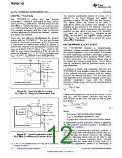
There are two different specifications for dropout
voltage with the TPS74801-Q1. The first specification
(shown in Figure 26) is referred to as VIN Dropout and
is used when an external bias voltage is applied to
achieve low dropout. This specification assumes that
VBIAS is at least 3.25V(1) above VOUT, which is the
case for VBIAS when powered by a 5.0V rail with 5%
tolerance and with VOUT = 1.5V. If VBIAS is higher than
VOUT +3.25V(1), VIN dropout is less than specified.
PROGRAMMABLE SOFT-START
The TPS74801-Q1 features
a
programmable,
monotonic, voltage-controlled soft-start that is set with
an external capacitor (CSS). This feature is important
for many applications because it eliminates power-up
initialization problems when powering FPGAs, DSPs,
or other processors. The controlled voltage ramp of
the output also reduces peak inrush current during
start-up, minimizing start-up transient events to the
input power bus.
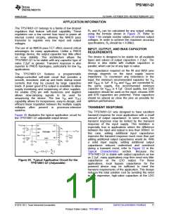
BIAS
IN
VBIAS = 5V ±5%
VIN = 1.8V
VOUT = 1.5V
IOUT = 1.5A
Reference
To achieve a linear and monotonic soft-start, the
TPS74801-Q1 error amplifier tracks the voltage ramp
of the external soft-start capacitor until the voltage
exceeds the internal reference. The soft-start ramp
time depends on the soft-start charging current (ISS),
soft-start capacitance (CSS), and the internal
reference voltage (VREF), and can be calculated using
Equation 1:
Efficiency = 83%
OUT
VOUT
COUT
FB
Simplified Block Diagram
(VREF ´ CSS
)
tSS
=
ISS
(1)
Figure 26. Typical Application of the
TPS74801-Q1 Using an Auxiliary Bias Rail
If large output capacitors are used, the device current
limit (ICL) and the output capacitor may set the
start-up time. In this case, the start-up time is given
by Equation 2:
VIN
(VOUT(NOM) ´ COUT
)
VBIAS = 3.3V ±5%
BIAS
IN
tSSCL =
VIN = 3.3V ± 5V
VOUT = 1.5V
ICL(MIN)
(2)
IOUT = 1.5A
where:
Reference
Efficiency = 45%
VOUT(NOM) is the nominal output voltage,
COUT is the output capacitance, and
OUT
VOUT
COUT
ICL(MIN) is the minimum current limit for the device.
FB
In applications where monotonic startup is required,
the soft-start time given by Equation 1 should be set
greater than Equation 2.
Simplified Block Diagram
The maximum recommended soft-start capacitor is
0.015μF. Larger soft-start capacitors can be used and
do not damage the device; however, the soft-start
capacitor discharge circuit may not be able to fully
discharge the soft-start capacitor when enabled.
Soft-start capacitors larger than 0.015μF could be a
problem in applications where it is necessary to
Figure 27. Typical Application of the
TPS74801-Q1 Without an Auxiliary Bias Rail
(1) 3.25V is a test condition of this device and can be adjusted by
referring to Figure 8.
12
Submit Documentation Feedback
© 2010–2011, Texas Instruments Incorporated
Product Folder Link(s): TPS74801-Q1

 TI [ TEXAS INSTRUMENTS ]