TPS65910, TPS65910A, TPS65910A3, TPS659101, TPS659102, TPS659103
TPS659104, TPS659105, TPS659106, TPS659107, TPS659108, TPS659109
www.ti.com
SWCS046N –MARCH 2010–REVISED APRIL 2012
DETAILED DESCRIPTION
POWER REFERENCE
The bandgap voltage reference is filtered by using an external capacitor connected across the VREF output and
the analog ground REFGND (see RECOMMENDED OPERATING CONDITIONS, Recommended Operating
Conditions). The VREF voltage is distributed and buffered inside the device.
POWER SOURCES
The power resources provided by the TPS65910 device include inductor-based switched mode power supplies
(SMPS) and linear low drop-out voltage regulators (LDOs). These supply resources provide the required power
to the external processor cores and external components, and to modules embedded in the TPS65910 device.
Two of these SMPS have DVS capability SmartReflex Class 3 compatible. These SMPS provide independent
core voltage domains to the host processor. The remaining SMPS provides supply voltage for the host processor
I/Os.
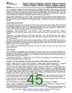
Table 12 lists the power sources provided by the TPS65910 device.
Table 12. Power Sources
RESOURCE
VIO
TYPE
SMPS
SMPS
VOLTAGES
POWER
1000 mA
1500 mA
1.5 V / 1.8 V / 2.5 V / 3.3 V
0.6 ... 1.5 in 12.5-mV steps
VDD1
Programmable multiplication factor: x2, x3
0.6 ... 1.5 in 12.5-mV steps
Programmable multiplication factor: x2, x3
5 V
VDD2
SMPS
1500 mA
VDD3
VDIG1
VDIG2
VPLL
SMPS
LDO
LDO
LDO
LDO
LDO
LDO
LDO
LDO
100 mA
300 mA
300 mA
50 mA
1.2 V, 1.5 V, 1.8 V, 2.7 V
1 V, 1.1 V, 1.2 V, 1.8 V
1.0 V, 1.1 V, 1.8 V, 2.5 V
1.8 V, 2.6 V, 2.8 V, 2.85 V
1.8 V, 2.5 V, 2.8 V, 2.85 V
1.8 V, 2.8 V, 2.9 V, 3.3 V
1.8 V, 2.0 V, 2.8 V, 3.3 V
1.8 V, 2.8 V, 3.0 V, 3.3 V
VDAC
150 mA
300 mA
150 mA
150 mA
300 mA
VAUX1
VAUX2
VAUX33
VMMC
EMBEDED POWER CONTROLLER
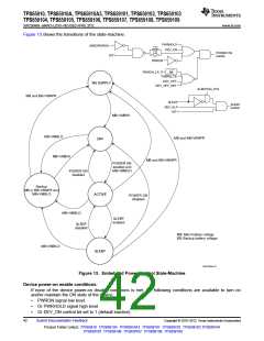
The embedded power controller manages the state of the device and controls the power-up sequence.
STATE-MACHINE
The EPC supports the following states:
No supply: The main battery supply voltage is not high enough to power the VRTC regulator. A global reset is
asserted in this case. Everything on the device is off.
Backup: The main battery supply voltage is high enough to enable the VRTC domain but not enough to switch
on all the resources. In this state, the VRTC regulator is in backup mode and only the 32-K oscillator and RTC
module are operating (if enabled). All other resources are off or under reset.
Off: The main battery supply voltage is high enough to start the power-up sequence but device power on is not
enabled. All power supplies are in OFF state except VRTC.
Active: Device power-on enable conditions are met and regulated power supplies are on or can be enabled with
full current capability.
Sleep: Device SLEEP enable conditions are met and some selected regulated power supplies are in low-power
mode.
Copyright © 2010–2012, Texas Instruments Incorporated
Submit Documentation Feedback
41
Product Folder Link(s): TPS65910 TPS65910A TPS65910A3 TPS659101 TPS659102 TPS659103 TPS659104
TPS659105 TPS659106 TPS659107 TPS659108 TPS659109

 TI [ TEXAS INSTRUMENTS ]