TPS61199
www.ti.com
SLVSAN3 –DECEMBER 2010
If any IFB pin voltage exceeds the threshold (VLED_short), the IC turns off the corresponding current sink and
removes this IFB pin from the output voltage regulation loop. Current regulation of the remaining IFB pins is
not affected.
If the voltage on all the IFB pins exceed the threshold, the IC repeatedly attempts to restart until the fault is
cleared.
4. Output over-voltage protection using the OVP pin:
Use a resistor divider to program the clamp threshold voltage as follows:
(a) Compute the maximum output voltage by multiplying the maximum forward voltage (VFWD(MAX)) and
number (n) of series LEDs. Add 1V to account for regulation and resistor tolerances and load transients.
VOUTMAX = VFLED_MAX ´Number +1V
(3)
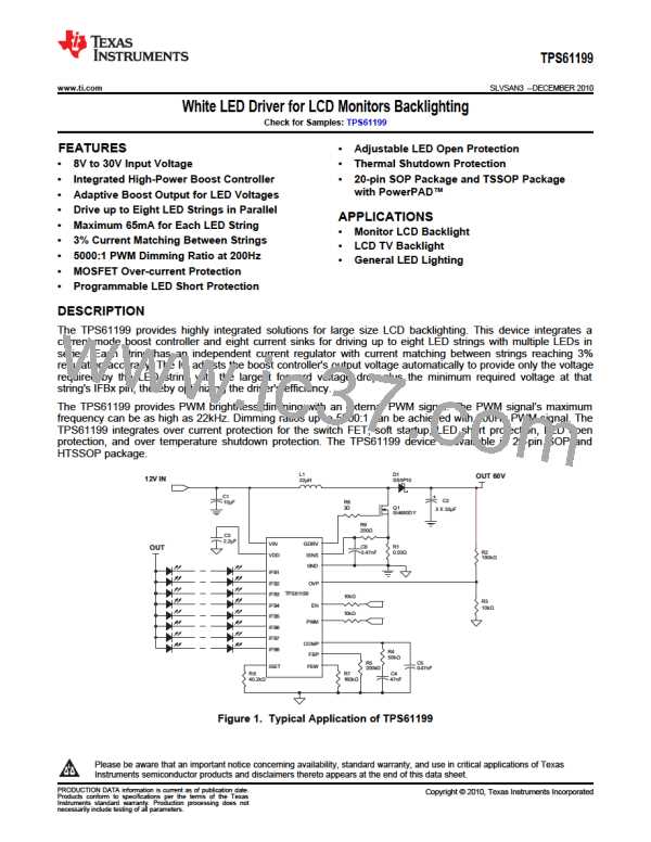
(b) The recommended bottom feedback resistor (R3, in the ) at 10k. Calculate the top resistor (R2, in the
Figure 1) using the following equation
V
OUTMAX +1V
æ
ç
è
ö
÷
ø
R2 =
-1 ´R3
2.95V
(4)
When the IC detects that the OVP pin exceeds 2.95V, indicating that the output voltage has exceeded the
clamp threshold voltage, the IC clamps the output voltage to the set threshold.
When the OVP pin voltage is higher than 3.0V, indicating that the output is higher than the clamp threshold
voltage due to transients or high voltage noise spike coupling from external circuits, the IC shuts down the
boost controller until the output drops below the clamp threshold voltage.
5. Output short to ground protection
When the inductor peak current reaches twice the switch current limit in each switch cycle, the IC
immediately disables the boost controller until the fault is cleared. This protects the IC and external
components from damage if the output is shorted to ground.
6. Thermal Protection
When the IC junction temperature is over 150°C, the thermal protection circuit is triggered and shuts down
the device immediately. The device automatically restarts when the junction temperature falls back to less
than 150°C, with approximate 15°C hysteresis.
Copyright © 2010, Texas Instruments Incorporated
Submit Documentation Feedback
11
Product Folder Link(s): TPS61199

 TI [ TEXAS INSTRUMENTS ]