TPS61199
SLVSAN3 –DECEMBER 2010
www.ti.com
Unused LED String
If the application requires less than eight LED strings, the TPS61199 simply requires shorting the unused IFB pin
to ground. The IC detects the voltage less than 0.3 V and immediately disables the string during startup. Refer to
Figure 12.
Program LED Full-Scale Current
The eight current sink regulators embedded in the TPS61199 can be configured to provide up to a maximum of
65mA per string. The current must be programmed to the expected full-scale LED current by the ISET pin
resistor, (R6, in Figure 1) using Equation 1.
VISET
ILED
=
´KISET
R6
(1)
Where:
KISET = Current multiple (1990 TYP, in the Electrical Characterization table)
VISET = ISET pin voltage (1.229V TYP, in the Electrical Characterization table)
PWM Dimming
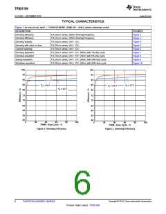
LED brightness dimming is set by applying an external PWM signal of 100Hz to 22kHz to the PWM pin. Varying
the PWM duty cycle from 0% to 100% adjusts the LED from minimum to maximum brightness respectively. The
minimum on time of the LED string is 1 µsec; thus the TPS61199 has a dimming ratio of 5000:1 at 200Hz. Refer
to Figure 5 for dimming ratio in other dimming frequency.
When the PWM voltage is pulled low, the IC will turn off the LED strings and keep the boost converter output at
the same level as when PWM is high. Thus, the TPS61199 limit the output ripple due to the load transient that
occurs during PWM dimming.
Drive High Current LED
For applications requiring LEDs rated for more than 65mA, it is acceptable to tie two or more IFB pins together
as shown in Figure 13.
Protection
1. Switch current limit protection using the ISNS pin
The TPS61199 monitors the inductor current through the voltage across a sense resistor (R1 in Figure 1) in
order to provide current limit protection. During the switch FET on period, when the voltage at ISNS pin rises
above 160 mV (VISNS in the Electrical Characterization table), the IC turns off the FET immediately and
does not turn it back on until the next switch cycle. The switch current limit is equal to 160mV / R1.
2. LED open protection
When one of the LED strings is open, the boost output rises to the clamp threshold voltage (see the Output
over-voltage protection using the OVP pin section). The IC detects the open string by sensing no current on
the corresponding IFB pin. As a result, the IC deactivates the open IFB pin and removes it from the voltage
feedback loop. Afterwards, the output voltage returns to the voltage required for the connected WLED
strings. The IFB pin currents of the connected strings remain in regulation during this process.
If all the LED strings are open, the IC repeatedly attempts to restart until the fault is cleared.
3. LED short-across protection using the FBP pin
If one or several LEDs short in one string, the corresponding IFB pin voltage rises but continues to sink the
LED current, causing increased IC power dissipation. To protect the IC, the TPS61199 provides a
programmable LED short-across protection feature with threshold voltage that can be programmed by
properly sizing the resistor on the FBP pin (See R5 in Figure 1) using the following equation.
R5
VLED_short
=
´1.229V
R6
(2)
10
Submit Documentation Feedback
Copyright © 2010, Texas Instruments Incorporated
Product Folder Link(s): TPS61199

 TI [ TEXAS INSTRUMENTS ]