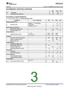
TPS5430-Q1
www.ti.com ................................................................................................................................................... SLVS751C–NOVEMBER 2007–REVISED JULY 2009
APPLICATION INFORMATION
FUNCTIONAL BLOCK DIAGRAM
VIN
VIN
VREF
SHDN
Boot
Regulator
1.221 V Bandgap
Reference
Slow Start
UVLO
BOOT
HICCUP
5 µA
ENABLE
SHDN
ENA
SHDN
VSENSE
Z1
Thermal
Protection
Error
Amplifier
SHDN
SHDN
Z2
Ramp
NC
VIN
Feed Forward
Gain = 25
Generator
NC
HICCUP
PWM
Comparator
SHDN
GND
Overcurrent
Protection
Oscillator
SHDN
SHDN
Gate Drive
Control
VSENSE
112.5% VREF
OVP
POWERPAD
Gate
Driver
SHDN
PH
BOOT
VOUT
DETAILED DESCRIPTION
Oscillator Frequency
The internal free running oscillator sets the PWM switching frequency at 500 kHz. The 500-kHz switching
frequency allows less output inductance for the same output ripple requirement resulting in a smaller output
inductor.
Voltage Reference
The voltage reference system produces a precision reference signal by scaling the output of a temperature
stable bandgap circuit. The bandgap and scaling circuits are trimmed during production testing to an output of
1.221 V at room temperature.
Enable (ENA) and Internal Slow Start
The ENA pin provides electrical on/off control of the regulator. Once ENA voltage exceeds the threshold voltage,
the regulator starts operation and the internal slow start begins to ramp. If ENA voltage is pulled below the
threshold voltage, the regulator stops switching and the internal slow start resets. Connecting the pin to ground
or to any voltage less than 0.5 V disables the regulator and activates the shutdown mode. The quiescent current
of the TPS5430 in shutdown mode is typically 18 µA.
Copyright © 2007–2009, Texas Instruments Incorporated
Submit Documentation Feedback
7
Product Folder Link(s): TPS5430-Q1

 TI [ TEXAS INSTRUMENTS ]