TPS51285A
TPS51285B
SLVSBX0 –APRIL 2013
www.ti.com
ULQ™ Mode
To achieve longer battery life in system stand-by mode of mobile devices, the device implements Ultra Low
Quiescent (ULQ) mode. In the ULQ mode, the device consumes low quiescent current (see the ELECTRICAL
CHARACTERISTICS table). Therefore, high efficiency can be obtained in the system stand-by mode. The
TPS51285A/B enters the ULQ mode automatically (no control input signal is required) when both high-side and
low-side MOSFET drivers are OFF state in discontinuous conduction operation. It exits from the ULQ mode when
the PWM comparator detects VFB drops to the internal 2-V VREF and turns on the high-side MOSFET. In the
ULQ mode, all protection functions are active.
D-CAP™ Mode
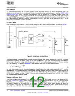
From small-signal loop analysis, a buck converter using D-CAP™ mode can be simplified as shown in Figure 3.
Switching Modulator
PWM
VIN
DRVH
DRVL
R1
R2
L
VFB
VOUT
Control
Logic
and
+
IOUT
IIND
Divider
IC
+
VREF
ESR
RLOAD
Voltage
Divider
VC
COUT
Output
Capacitor
Figure 3. Simplifying the Modulator
The output voltage is compared with internal reference voltage after divider resistors, R1 and R2. The PWM
comparator determines the timing to turn on the high-side MOSFET. The gain and speed of the comparator is
high enough to keep the voltage at the beginning of each ON cycle substantially constant. For the loop stability,
the 0 dB frequency, ƒ0, defined in Equation 2 must be lower than 1/4 of the switching frequency.
f
1
SW
f =
£
0
2p´ESR ´C
4
OUT
(2)
As ƒ0 is determined solely by the output capacitor characteristics, the loop stability during D-CAP™ mode is
determined by the capacitor chemistry. For example, specialty polymer capacitors have output capacitance in the
order of several hundred micro-Farads and ESR in range of 10 milli-ohms. These yield an f0 value on the order
of 100 kHz or less and the loop is stable. However, ceramic capacitors have ƒ0 at more than 700 kHz, which is
not suitable for this operational mode.
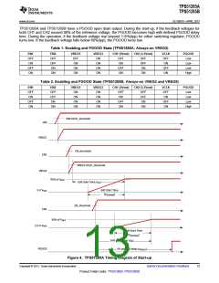
Enable and Power Good
VREG3 is an always-on regulator (TPS51285A and TPS1285B), For TPS51285B, VREG5 is an always-on LDO,
too (See Table 1 and Table 2). When VIN exceeds the VIN-UVLO threshold VREG3 turns on. For TPS51285B,
VREG5 turns on when VREG3 exceeds 2.4V. For TPS51285A, VREG5 turns on when either EN1 or EN2 enters
ON state in addition to the above VREG3 threshold. CH1’s or CH2’s output starts ramping up when the
corresponding EN pin is in the ON state and VREG5 is larger than the VREG5-UVLO. VCLK initiates switching
when EN1 enters ON state. The state controls are shown in Table 1 and Table 2.
12
Submit Documentation Feedback
Copyright © 2013, Texas Instruments Incorporated
Product Folder Links: TPS51285A TPS51285B

 TI [ TEXAS INSTRUMENTS ]