TPS43060
TPS43061
SLVSBP4A –DECEMBER 2012–REVISED DECEMBER 2012
www.ti.com
LOW DROPOUT REGULATOR
The TPS43060 and TPS43061 contain a low dropout regulators that provides bias supply for the controller and
the gate driver. The output of the LDO of TPS43060 and TPS43061 are regulated to 7.5 V and 5.5 V,
respectively. When the input voltage is below the VCC regulation level the VCC output tracks VIN with a small
dropout voltage. The output current of the VCC regulator should not exceed 50 mA. The value of the VCC
capacitance depends on the total system design, and its startup characteristics. The recommended range of
values for the VCC capacitor is from 0.47 µF to 10 µF.
INPUT UNDERVOLTAGE (UV)
An undervoltage detection circuit prevents mis-operation of the device at input voltages below 3.9 V (typical).
When the input voltage is below the VIN UV threshold, the internal PWM control circuitry and gate drivers are
turned off. The threshold is set below minimum operating voltage of 4.5 V to ensure that a transient VIN dip will
not cause the device to reset. For input voltages between the UV threshold and 4.5 V, the device attempts to
operate, but the electrical specifications are not ensured. The EN pin can be used to achieve adjustable UVLO if
the desired start-up threshold is higher than 3.9 V. Details are provided in the following section.
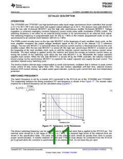
ENABLE AND ADJUSTABLE UNDERVOLTAGE LOCKOUT (UVLO)
The EN pin voltage must be greater than 1.21 V (typical) to enable TPS43060 and TPS43061. The device enters
a shutdown mode when the EN voltage is less than 0.4 V. In shutdown mode, the input supply current for the
device is less than 5 µA. The EN pin has an internal 1.8 μA pull-up current source that provides the default
enabled condition when the EN pin floats. When the EN pin voltage is higher than the shutdown threshold but
less than 1.21 V, the devices are in standby mode.
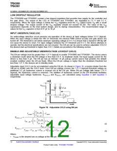
Adjustable input UVLO can be accomplished using the EN pin. As shown in Figure 18, a resistor divider from the
VIN pin to AGND sets the UVLO level. Once EN pin voltage crosses the 1.21 V (typical) threshold voltage an
additional 3.2 μA hysteresis current is sourced out of the EN pin. When EN pin voltage falls below 1.14 V
(typical), the hysteresis current is removed. The addition of hysteresis current at the EN threshold facilitates
adjustable input voltage hysteresis. RUVLO_H and RUVLO_L are calculated using Equation 2 and Equation 3
respectively.
VIN
RUVLO_H
3.2 µA
1.8 µA
EN
1.21 V
RUVLO_L
AGND
Figure 18. Adjustable UVLO using EN pin
æ
ö
VEN _ DIS
VSTART
´
æ
-V
ç
÷
STOP
ç
÷
VEN _ON
è
ø
RUVLO _ H
=
ö
VEN _ DIS
IEN _ pup ´ 1-
+ I
EN _ hys
ç
÷
ç
è
÷
VEN _ON
ø
REN _ H ´VEN _ DIS
(2)
(3)
RUVLO _ L
=
VSTOP -VEN _ DIS + REN _ H ´ IEN _ pup + IEN _ hys + I
)
(
EN _ hys
Where
•
VSTART is the desired turn-on voltage at the VIN pin
12
Submit Documentation Feedback
Copyright © 2012, Texas Instruments Incorporated
Product Folder Links: TPS43060 TPS43061

 TI [ TEXAS INSTRUMENTS ]