TPS386000-Q1
www.ti.com
SBVS149 –SEPTEMBER 2010
RESET OUTPUT
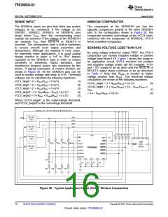
minimal propagation delay. Figure 27 describes
relationship between threshold voltages (VITN and
VHYSN) and SENSEm voltage; and all SVS-1, SVS-2,
SVS-3, and SVS-4 have the same behavior of
Figure 27.
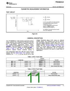
In a typical TPS386000-Q1 application, RESETn or
RESETn outputs are connected to the reset input of a
processor (DSP, CPU, FPGA, ASIC, etc.), or
connected to the enable input of a voltage regulator
(DC-DC, LDO, etc.)
VCC
The TPS386000-Q1 provides open-drain reset
outputs. Pull-up resistors must be used to hold these
lines high when RESETn is not asserted, or when
RESETn is asserted. By connecting pull-up resistors
to the proper voltage rails (up to 6.5V), RESETn or
RESETn output nodes can be connected to the other
devices at the correct interface voltage levels. The
pull-up resistor should be no smaller than 10kΩ
because of the safe operation of the output
transistors. By using wired-OR logic, any combination
of RESETn can be merged into one logic signal.
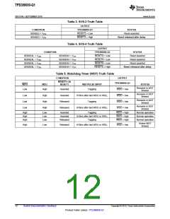
0.9V
t
SENSE1
VHYSN
VITN
The TPS386000-Q1 provides push-pull reset outputs.
The logic high level of the outputs is determined by
the VCC voltage. With this configuration, pull-up
resistors are not required and some board area can
be saved. However, all the interface logic levels
should be examined. All RESETn or RESETn
connections must be compatible with the VCC logic
level.
t
MR
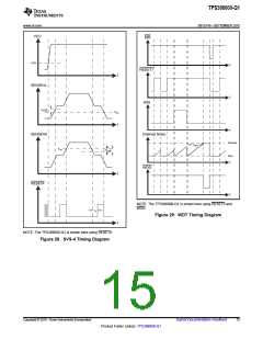
The RESETn or RESETn outputs are defined for
VCC voltage higher than 0.9V. To ensure that the
target processor(s) are properly reset, the VCC
supply input should be fed by the available power rail
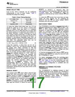
as early as possible in application circuits. Table 1,
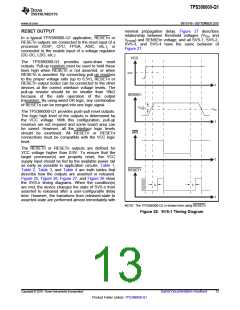
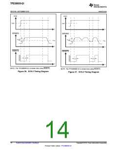
Table 2, Table 3, and Table 4 are truth tables that
describe how the outputs are asserted or released.
Figure 25, Figure 26, Figure 27, and Figure 28 show
the SVS-n timing diagrams. When the condition(s)
are met, the device changes the state of SVS-n from
asserted to released after a user-configurable delay
time. However, the transitions from released-state to
asserted-state are performed almost immediately with
t
RESET1
tD
tD
t
NOTE: The TPS386000-Q1 is shown here using RESETn.
Figure 25. SVS-1 Timing Diagram
Copyright © 2010, Texas Instruments Incorporated
Submit Documentation Feedback
13
Product Folder Link(s): TPS386000-Q1

 TI [ TEXAS INSTRUMENTS ]