TPS386000-Q1
www.ti.com
SBVS149 –SEPTEMBER 2010
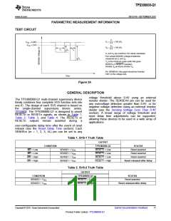
PARAMETRIC MEASUREMENT INFORMATION
TEST CIRCUIT
Z1
X1
X2
=
=
´ 100 (%)
´ 100 (%)
VITN = 0.42V
VITN = 0.4V
0.4
Z2
0.4
Y1
Y2
Z1
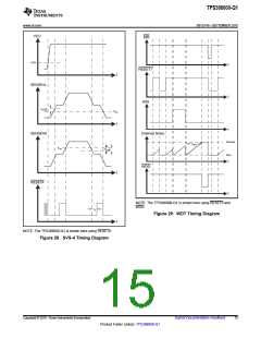
X1 and X2 are overdrive (%) values calculated
from actual SENSEn voltage amplitudes
measured as Z1 and Z2.
Z2
YN is the minimum pulse width that gives
RESETn or RESETn transition.
Greater ZN produces shorter YN.
For SENSE4H, this graph should be inverted
180° on the voltage axis.
Time
Figure 24.
GENERAL DESCRIPTION
voltage threshold above 0.4V using an external
resistor divider. The SENSE4H pin can be used for
any overvoltage detection greater than 0.4V, or for
negative voltage detection using an external resistor
divider (see the Sensing Voltage Less Than 0.4V
section). A broad range of voltage threshold and
reset delay time adjustments can be supported,
allowing these devices to be used in a wide array of
applications.
The TPS386000-Q1 multi-channel supervisory device
family combines four complete SVS function sets into
one IC. The design of each SVS channel is based on
the single-channel supervisory device series,
TPS3808. The TPS386000-Q1 is designed to assert
RESETn or RESETn signals, as shown in Table 1,
Table 2, Table 3, and Table 4. The RESETn or
RESETn outputs remain asserted during
a
user-configurable delay time after the event of reset
release (see the Reset Delay Time section). Each
SENSEm (m = 1, 2, 3, 4L) pin can be set to any
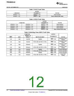
Table 1. SVS-1 Truth Table
OUTPUT
CONDITION
TPS386000-Q1
RESET1 = Low
RESET1 = Low
RESET1 = Low
RESET1 = High
STATUS
Reset asserted
MR = Low
MR = Low
MR = High
MR = High
SENSE1 < VITN
SENSE1 > VITN
SENSE1 < VITN
SENSE1 > VITN
Reset asserted
Reset asserted
Reset released after delay
Table 2. SVS-2 Truth Table
OUTPUT
CONDITION
TPS386000-Q1
RESET2 = Low
RESET2 = High
STATUS
SENSE2 < VITN
SENSE2 > VITN
Reset asserted
Reset released after delay
Copyright © 2010, Texas Instruments Incorporated
Submit Documentation Feedback
11
Product Folder Link(s): TPS386000-Q1

 TI [ TEXAS INSTRUMENTS ]