TPS23753A
www.ti.com
SLVS933B –JULY 2009–REVISED JANUARY 2010
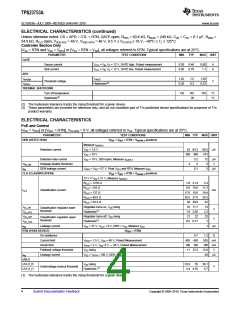
ELECTRICAL CHARACTERISTICS (continued)
PoE and Control
[VDD = VDD1] or [VDD1 = RTN], VVC-RTN = 0 V, all voltages referred to VSS. Typical specifications are at 25°C.
PARAMETER
TEST CONDITIONS
MIN TYP MAX UNIT
THERMAL SHUTDOWN
Turn off temperature
Hysteresis(2)
135 145
20
155
°C
°C
(2) These parameters are provided for reference only.
DEVICE INFORMATION
TOP VIEW
CTL
V
B
14
13
12
11
10
9
FRS
BLNK
APD
CLS
1
2
3
4
5
6
7
CS
V
C
GATE
RTN
DEN
V
V
DD
DD1
V
8
SS
Table 1. Terminal Functions
TERMINAL
I/O
DESCRIPTION
NO.
NAME
1
CTL
I
The control loop input to the PWM (pulse width modulator). Use VB as a pull up for CTL.
5 V bias rail for dc/dc control circuits. Apply a 0.1 mF to RTN. VB may be used to bias an external
optocoupler for feedback.
2
VB
O
Dc/dc converter switching MOSFET current sense input. Connect CS to the high side of RCS per
Figure 1.
3
4
CS
I
Dc/dc converter bias voltage. The internal startup current source and converter bias winding output
power this pin. Connect a 0.22 mF minimum ceramic capacitor to RTN, and a larger capacitor to
facilitate startup.
VC
I/O
O
5
6
7
8
9
GATE
RTN
VSS
Gate drive output for the dc/dc converter switching MOSFET.
RTN is the negative rail input to the dc/dc converter and output of the PoE hotswap.
Negative power rail derived from the PoE source.
VDD1
VDD
Source of dc/dc converter startup current. Connect to VDD for most applications.
Positive input power rail for PoE interface circuit. Derived from the PoE source.
Connect a 24.9 kΩ resistor from DEN to VDD to provide the PoE detection signature. Pulling this pin
to VSS during powered operation causes the internal hotswap MOSFET to turn off.
10
11
12
DEN
CLS
APD
I/O
O
I
Connect a resistor from CLS to VSS to program the classification current per Table 2.
Pull APD above 1.5 V to disable the internal PD hotswap switch, forcing power to come from an
external adapter. Connect to the adapter through a resistor divider.
Connect to RTN to utilize the internally set blanking period or connect through a resistor to RTN to
program the blanking period.
13
14
BLNK
FRS
I/O
I/O
Connect a resistor from FRS to RTN to program the converter switching frequency.
Copyright © 2009–2010, Texas Instruments Incorporated
Submit Documentation Feedback
5

 TI [ TEXAS INSTRUMENTS ]