TPS1HC100-Q1
ZHCSLK6A –JULY 2021 –REVISED DECEMBER 2021
www.ti.com.cn
• Internal current limit: ILIM pin shorted to ground –if the external current limit is out of range on the lower end
or the ILIM pin is shorted to ground, the internal current limit is fixed and typically 7 A. To use the internal
current limit for large-current applications, tie the ILIM pin directly to the device GND.
• Internal current limit: ILIM pin open –if the external resistor is out of range on the higher end or the ILIM pin
is open, the current limit reverts to 3 A or half the current limit range. This level is still above the nominal
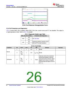
operation for the device to operate in DC steady state but is low enough that if a pin fault occurs and the RILIM
opens up, the current does not default to the highest rating and put additional stress on the power supply.
Both the internal current limit (Ilim,nom) and external programmable current limit are always active when VBB is
powered and EN is high. The lower value one (of ILIM and the external programmable current limit) is applied as
the actual current limit. The typical deglitch time for the current limit to assert is 2.5 µs.
Note that if a GND network is used (which leads to the level shift between the device GND and board GND), the
ILIM pin must be connected with device GND. Calculate RILIM with Equation 2.
RILIM = KCL / ILIM
(2)
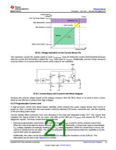
For better protection from a hot short condition (when VBB is high, channel is on, and a short to GND happens
suddenly), an over current protection, OVCR, circuit is triggered that makes sure to limit the maximum current
the device allows to go through. With this OVCR, the device is protected during hot short events.
For more information about the current limiting feature, see the Short-Circuit and Overload Protection section.
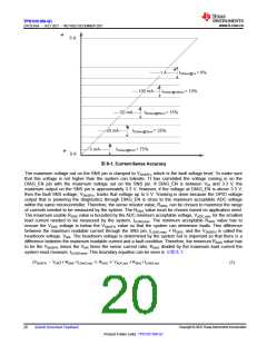
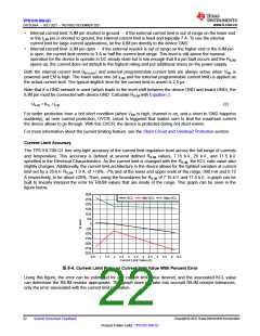
Current Limit Accuracy
The TPS1HC100-Q1 has very tight accuracy of the current limit regulation level across the full range of currents
and temperature. This accuracy is defined at several defined RILIM values, 7.15 kΩ, 25 kΩ, and 71.5 kΩ
specified in the Electrical Characteristics. As the current limit is changed with the RILIM, the KCL ratio value also
slightly changes. Additionally, the current limit architecture in the device allows for the tightest variation at current
limit set by a 25-kΩ RILIM, 1.9 A, of +18%, -7% and at the lower and upper ends of the range, 690 mA and 6.15
A respectively, to be about ±25%. Then, using the boundaries for RILIM of 7.15 kΩand 71.5 kΩ, a graph can be
built to linearly interpret the error for RILIM values that are inside of the range. This graph can be seen in the
figure below.
30%
KCL
Min KCL
Max KCL
25%
20%
15%
10%
5%
0
-5%
-10%
-15%
-20%
-25%
-30%
0.5
1
1.5
2
2.5
3
3.5
4
4.5
5
5.5
6
6.5
Current Limit Value (A)
图8-4. Current Limit Ratio vs Current limit Value With Percent Error
Using this figure, the error can be estimated for any current limit value desired, and the associated KCL value
can determine the RILIM resistor appropriate. This graph does not take into account RILIM resistor tolerances,
only the error associated with the current limit regulation.
Copyright © 2022 Texas Instruments Incorporated
22
Submit Document Feedback
Product Folder Links: TPS1HC100-Q1

 TI [ TEXAS INSTRUMENTS ]