TPS1H100-Q1
www.ti.com.cn
ZHCSDD8D –OCTOBER 2014–REVISED DECEMBER 2019
Typical Application (continued)
8.2.1 Design Requirements
•
•
•
•
•
•
VS range from 9 V to 16 V
Nominal current of 2 A
Current sense for fault monitoring
Expected current limit value of 5 A
Full diagnostics with 5-V MCU
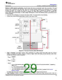
Reverse protection with GND network
8.2.2 Detailed Design Procedure
The RCS, VCS linear region is from 0 to 4 V. To keep the 2-A nominal current in the 0- to 3-V range, calculate the
RCS as in Equation 11. To achieve better current sense accuracy, a 1% accuracy or better resistor is preferred.
VCS VCS ì K
3 ì 500
RCS
=
=
=
= 750 W
ICS
IOUT
2
(11)
RCL, VCL,th is the current-limit internal threshold, 1.233 V. To set the programmable current limit value at 5 A,
calculate the RCL as in Equation 12.
Vcl,th ì KCL
1.233 ì 2000
RCL
=
=
= 493.2 W
IOUT
5
(12)
TI recommends RSER = 10 kΩ for 5-V MCU.
TI recommends a 1-kΩ resistor and 200-V, 0.2-A diode for the GND network.
8.2.2.1 Distinguishing of Different Fault Modes
Some applications require that open load, short to battery, and short to GND can be distinguished from each
other. This requires two steps:
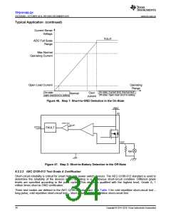
1. In the on-state, for the current-sense version device (version B), on-state open load and short to battery are
recognized as an extremely-low voltage level on the current-sense pin, whereas short to GND is reported as
a pulled-up voltage VCS,h. Therefore, the user can find a short to GND (see Figure 46).
2. If reported as an on-state open-load or short-to-battery fault in the first step, turn off the input signal. In the
off-state, with an external pulldown resistor, open load and short to battery can be easily distinguished. When
the output pulls down, the short to battery is still reported as an off-state fault condition, whereas the open
load is ignored.
Copyright © 2014–2019, Texas Instruments Incorporated
33

 TI [ TEXAS INSTRUMENTS ]