TPS1H100-Q1
ZHCSDD8D –OCTOBER 2014–REVISED DECEMBER 2019
www.ti.com.cn
8 Application and Implementation
NOTE
Information in the following applications sections is not part of the TI component
specification, and TI does not warrant its accuracy or completeness. TI’s customers are
responsible for determining suitability of components for their purposes. Customers should
validate and test their design implementation to confirm system functionality.
8.1 Application Information
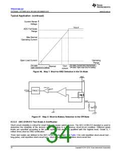
The following discussion notes how to implement the device to distinguish the different fault modes and
implement a ? transient-pulse immunity test.
In some applications, open load, short to battery, and short to GND must be distinguished from each other. This
requires two steps.
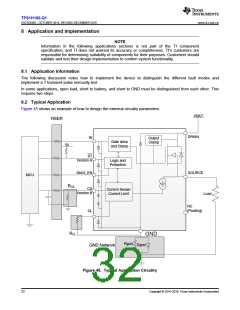
8.2 Typical Application
Figure 45 shows an example of how to design the external circuitry parameters.
VBAT
RSER
DRAIN
IN
Output
Clamp
Gate drive
and Clamp
5V
ST
Version A
Logic and
Protection
DIAG_EN
SOURCE
MCU
RCS
CS
Version B
Current Sense/
Current Limit
Load
NC
(Floating)
CL
RCL
GND
Rgnd
Dgnd
GND Network
Figure 45. Typical Application Circuitry
32
Copyright © 2014–2019, Texas Instruments Incorporated

 TI [ TEXAS INSTRUMENTS ]