TMS320TCI6487
TMS320TCI6488
Communications Infrastructure Digital Signal Processor
SPRS358F–APRIL 2007–REVISED AUGUST 2008
www.ti.com
8.5 Interrupts
8.5.1 Interrupt Sources and Interrupt Controller
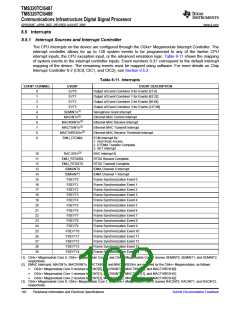
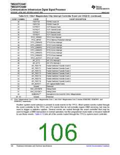
The CPU interrupts on the device are configured through the C64x+ Megamodule Interrupt Controller. The
interrupt controller allows for up to 128 system events to be programmed to any of the twelve CPU
interrupt inputs, the CPU exception input, or the advanced emulation logic. Table 8-11 shows the mapping
of system events to the interrupt controller inputs. Event numbers 0-31 correspond to the default interrupt
mapping of the device. The remaining events must be mapped using software. For more details on Chip
Interrupt Controller 0-2 (CIC0, CIC1, and CIC2), see Section 8.5.2.
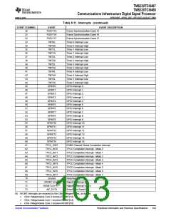
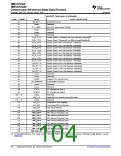
Table 8-11. Interrupts
EVENT CHANNEL
EVENT
EVT0
EVENT DESCRIPTION
Output of Event Combiner 0 for Events [31:4]
0
1
2
3
4
5
6
7
8
9
EVT1
Output of Event Combiner 1 for Events [63:32]
Output of Event Combiner 2 for Events [95:64]
Output of Event Combiner 3 for Events [127:96]
Semaphore Grant Interrupt
EVT2
EVT3
SEMINTn(1)
MACINTn(2)
MACRXINTn(2)
MACTXINTn(2)
MACTHRESHn(2)
EMU_DTDMA
Ethernet MAC Control Interrupt
Ethernet MAC Receive Interrupt
Ethernet MAC Transmit Interrupt
Ethernet MAC Receive Threshold Interrupt
ECM Interrupt for:
1. Host Scan Access
2. DTDMA Transfer Complete
3. AET Interrupt
10
11
12
13
14
15
16
17
18
19
20
21
22
23
24
25
26
27
28
29
RAC INTn(3)
EMU_RTDXRX
EMU_RTDXTX
IDMAINT0
IDMAINT1
FSEVT0
RAC Interrupt N
RTDX Receive Complete
RTDX Transmit Complete
IDMA Channel 0 Interrupt
IDMA Channel 1 Interrupt
Frame Synchronization Event 0
Frame Synchronization Event 1
Frame Synchronization Event 2
Frame Synchronization Event 3
Frame Synchronization Event 4
Frame Synchronization Event 5
Frame Synchronization Event 6
Frame Synchronization Event 7
Frame Synchronization Event 8
Frame Synchronization Event 9
Frame Synchronization Event 10
Frame Synchronization Event 11
Frame Synchronization Event 12
Frame Synchronization Event 13
Frame Synchronization Event 14
FSEVT1
FSEVT2
FSEVT3
FSEVT4
FSEVT5
FSEVT6
FSEVT7
FSEVT8
FSEVT9
FSEVT10
FSEVT11
FSEVT12
FSEVT13
FSEVT14
(1) C64x+ Megamodule Core 0, C64x+ Megamodule Core 1, and C64x+ Megamodule Core 2 receive SEMINT0, SEMINT1, and SEMINT2,
respectively.
(2) EMAC interrupts, MACINTn, MACRXINTn, MACTXINTn, and MACTHRESHn are received by the C64x+ Megamodules, as follows:
•
•
•
C64x+ Megamodule Core 0 receives MACINT[0], MACRXINT[0], MACTXINT[0], and MACTHRESH[0]
C64x+ Megamodule Core 1 receives MACINT[1], MACRXINT[1], MACTXINT[1], and MACTHRESH[1]
C64x+ Megamodule Core 2 receives MACINT[2], MACRXINT[2], MACTXINT[2], and MACTHRESH[2]
(3) C64x+ Megamodule Core 0, C64x+ Megamodule Core 1, and C64x+ Megamodule Core 2 receive RACINT0, RACINT1, and RACINT2,
respectively.
102
Peripheral Information and Electrical Specifications
Submit Documentation Feedback

 TI [ TEXAS INSTRUMENTS ]