ꢀ ꢁꢂ ꢃ ꢄ ꢅ ꢆꢇ ꢄ ꢈꢈ ꢉ ꢀ ꢁꢂ ꢃ ꢄꢅ ꢆꢇ ꢄꢈꢈꢊ
ꢋ ꢌꢍ ꢎꢏꢐꢑꢒ ꢌ ꢓꢀ ꢏꢌ ꢔꢌ ꢀꢕꢖ ꢂꢌ ꢔ ꢓꢕꢖ ꢑꢗ ꢒ ꢆꢎ ꢂ ꢂꢒ ꢗ ꢂ
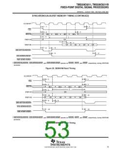
SPRS073L − AUGUST 1998 − REVISED JUNE 2005
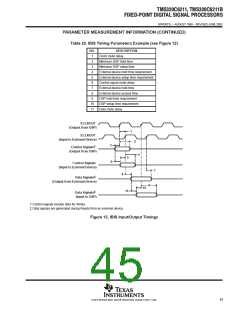
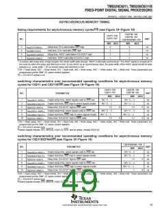
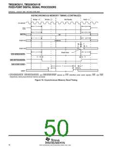
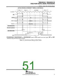
ASYNCHRONOUS MEMORY TIMING
†‡§
timing requirements for asynchronous memory cycles
(see Figure 18−Figure 19)
C6211B−150
C6211−150
C6211B−167
C6211BGFNA−150
C6211−167
NO.
UNIT
MIN MAX
MIN
9
MAX
3
4
6
7
t
t
t
t
Setup time, EDx valid before ARE high
Hold time, EDx valid after ARE high
9
1
3
1
ns
ns
ns
ns
su(EDV-AREH)
h(AREH-EDV)
su(ARDY-EKOH)
h(EKOH-ARDY)
2
Setup time, ARDY valid before ECLKOUT high
Hold time, ARDY valid after ECLKOUT high
3
2
†
To ensure data setup time, simply program the strobe width wide enough. ARDY is internally synchronized. The ARDY signal is recognized in
the cycle for which the setup and hold time is met. To use ARDY as an asynchronous input, the pulse width of the ARDY signal should be wide
enough (e.g., pulse width = 2E) to ensure setup and hold time is met.
‡
§
RS = Read setup, RST = Read strobe, RH = Read hold, WS = Write setup, WST = Write strobe, WH = Write hold. These parameters are
programmed via the EMIF CE space control registers.
E = ECLKOUT period in ns
switching characteristics over recommended operating conditions for asynchronous memory
द
cycles for C6211 and C6211B
(see Figure 18−Figure 19)
C6211−150
C6211−167
C6211B−150
C6211B−167
NO.
PARAMETER
UNIT
MIN
MAX
MIN
RS * E − 3
RH * E − 3
1.5
MAX
1
2
t
t
t
t
t
t
Output setup time, select signals valid to ARE low
Output hold time, ARE high to select signals invalid
Delay time, ECLKOUT high to ARE vaild
RS * E − 3
ns
ns
ns
ns
ns
ns
osu(SELV-AREL)
oh(AREH-SELIV)
d(EKOH-AREV)
osu(SELV-AWEL)
oh(AWEH-SELIV)
d(EKOH-AWEV)
RH * E − 3
1.5
5
8
8
8
Output setup time, select signals valid to AWE low
Output hold time, AWE high to select signals invalid
Delay time, ECLKOUT high to AWE vaild
WS * E − 3
WH * E − 3
1.5
WS * E − 3
WH * E − 3
1.2
9
10
8
8
‡
RS = Read setup, RST = Read strobe, RH = Read hold, WS = Write setup, WST = Write strobe, WH = Write hold. These parameters are
programmed via the EMIF CE space control registers.
E = ECLKOUT period in ns
§
¶
Select signals include: CEx, BE[3:0], EA[21:2], AOE; and for writes, include ED[31:0].
switching characteristics over recommended operating conditions for asynchronous memory
द
cycles for C6211BGFNA
(see Figure 18−Figure 19)
C6211BGFNA−150
NO.
PARAMETER
UNIT
MIN
RS * E − 3
RH * E − 3
1.5
MAX
1
2
t
t
t
t
t
t
Output setup time, select signals valid to ARE low
Output hold time, ARE high to select signals invalid
Delay time, ECLKOUT high to ARE vaild
ns
ns
ns
ns
ns
ns
osu(SELV-AREL)
oh(AREH-SELIV)
d(EKOH-AREV)
osu(SELV-AWEL)
oh(AWEH-SELIV)
d(EKOH-AWEV)
5
8
8
Output setup time, select signals valid to AWE low
Output hold time, AWE high to select signals invalid
Delay time, ECLKOUT high to AWE vaild
WS * E − 3
WH * E − 3
1
9
10
8
‡
RS = Read setup, RST = Read strobe, RH = Read hold, WS = Write setup, WST = Write strobe, WH = Write hold. These parameters are
programmed via the EMIF CE space control registers.
§
¶
E = ECLKOUT period in ns
Select signals include: CEx, BE[3:0], EA[21:2], AOE; and for writes, include ED[31:0].
49
POST OFFICE BOX 1443 • HOUSTON, TEXAS 77251−1443

 TI [ TEXAS INSTRUMENTS ]