ꢀ ꢁꢂ ꢃ ꢄ ꢅ ꢆꢇ ꢄ ꢈꢈ ꢉ ꢀ ꢁꢂ ꢃ ꢄꢅ ꢆꢇ ꢄꢈꢈꢊ
ꢋ ꢌꢍ ꢎꢏꢐꢑꢒ ꢌ ꢓꢀ ꢏꢌ ꢔꢌ ꢀꢕꢖ ꢂꢌ ꢔ ꢓꢕꢖ ꢑꢗ ꢒ ꢆꢎ ꢂ ꢂꢒ ꢗ ꢂ
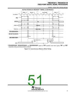
SPRS073L − AUGUST 1998 − REVISED JUNE 2005
INPUT AND OUTPUT CLOCKS (CONTINUED)
†‡§
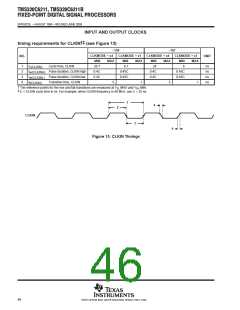
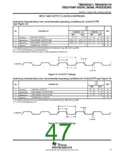
switching characteristics over recommended operating conditions for CLKOUT1
(see Figure 14)
−150
−167
NO.
PARAMETER
UNIT
CLKMODE = x4
CLKMODE = x1
MIN
MAX
P + 0.7
MIN
MAX
1
2
3
4
t
t
t
t
Cycle time, CLKOUT1
P − 0.7
P − 0.7
P + 0.7
ns
ns
ns
ns
c(CKO1)
w(CKO1H)
w(CKO1L)
t(CKO1)
Pulse duration, CLKOUT1 high
Pulse duration, CLKOUT1 low
Transition time, CLKOUT1
(P/2) − 0.7 (P/2 ) + 0.7 PH − 0.7 PH + 0.7
(P/2) − 0.7 (P/2 ) + 0.7
2
PL − 0.7 PL + 0.7
2
†
‡
§
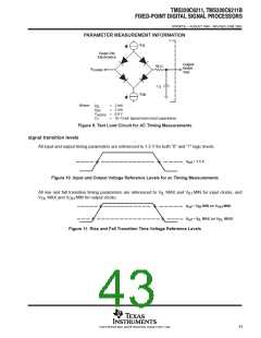
The reference points for the rise and fall transitions are measured at V
P = 1/CPU clock frequency in nanoseconds (ns)
PH is the high period of CLKIN in ns and PL is the low period of CLKIN in ns.
MAX and V MIN.
OH
OL
1
4
2
CLKOUT1
3
4
Figure 14. CLKOUT1 Timings
†‡
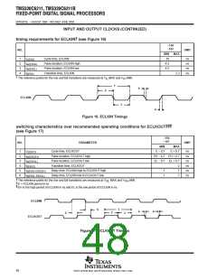
switching characteristics over recommended operating conditions for CLKOUT2 (see Figure 15)
−150
−167
NO.
PARAMETER
UNIT
MIN
MAX
1
2
3
4
t
t
t
t
Cycle time, CLKOUT2
2P − 0.7 2P + 0.7
ns
ns
ns
ns
c(CKO2)
w(CKO2H)
w(CKO2L)
t(CKO2)
Pulse duration, CLKOUT2 high
Pulse duration, CLKOUT2 low
Transition time, CLKOUT2
P − 0.7
P − 0.7
P + 0.7
P + 0.7
2
†
‡
The reference points for the rise and fall transitions are measured at V
P = 1/CPU clock frequency in ns
MAX and V
MIN.
OL
OH
1
4
2
CLKOUT2
3
4
Figure 15. CLKOUT2 Timings
47
POST OFFICE BOX 1443 • HOUSTON, TEXAS 77251−1443

 TI [ TEXAS INSTRUMENTS ]