TMS320F28027, TMS320F28027-Q1, TMS320F28027F, TMS320F28027F-Q1, TMS320F28026
TMS320F28026-Q1, TMS320F28026F, TMS320F28026F-Q1, TMS320F28023
TMS320F28023-Q1, TMS320F28022, TMS320F28021, TMS320F28020, TMS320F280200
ZHCSA13P –NOVEMBER 2008 –REVISED FEBRUARY 2021
www.ti.com.cn
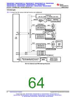
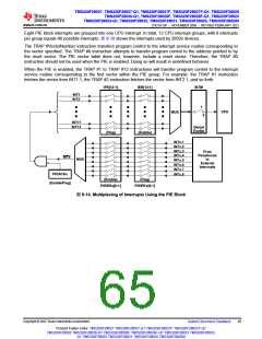
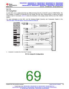
Eight PIE block interrupts are grouped into one CPU interrupt. In total, 12 CPU interrupt groups, with 8 interrupts
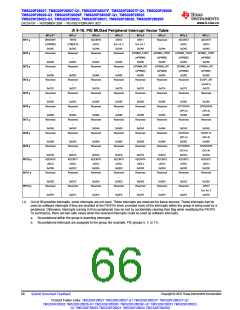
per group equals 96 possible interrupts. 表9-18 shows the interrupts used by 2802x devices.
The TRAP #VectorNumber instruction transfers program control to the interrupt service routine corresponding to
the vector specified. The TRAP #0 instruction attempts to transfer program control to the address pointed to by
the reset vector. The PIE vector table does not, however, include a reset vector. Therefore, the TRAP #0
instruction should not be used when the PIE is enabled. Doing so will result in undefined behavior.
When the PIE is enabled, the TRAP #1 to TRAP #12 instructions will transfer program control to the interrupt
service routine corresponding to the first vector within the PIE group. For example: the TRAP #1 instruction
fetches the vector from INT1.1, the TRAP #2 instruction fetches the vector from INT2.1, and so forth.
IFR[12:1]
IER[12:1]
INTM
INT1
INT2
1
CPU
MUX
0
INT11
INT12
Global
Enable
(Flag)
(Enable)
INTx.1
INTx.2
INTx.3
INTx.4
INTx.5
From
Peripherals
or
External
Interrupts
INTx
MUX
INTx.6
INTx.7
INTx.8
PIEACKx
(Enable/Flag)
(Enable)
(Flag)
PIEIERx[8:1]
PIEIFRx[8:1]
图9-14. Multiplexing of Interrupts Using the PIE Block
Copyright © 2022 Texas Instruments Incorporated
Submit Document Feedback
65
Product Folder Links: TMS320F28027 TMS320F28027-Q1 TMS320F28027F TMS320F28027F-Q1
TMS320F28026 TMS320F28026-Q1 TMS320F28026F TMS320F28026F-Q1 TMS320F28023 TMS320F28023-
Q1 TMS320F28022 TMS320F28021 TMS320F28020 TMS320F280200

 TI [ TEXAS INSTRUMENTS ]