TMS320C6678
Multicore Fixed and Floating-Point Digital Signal Processor
SPRS691D—April 2013
www.ti.com
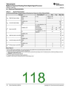
6.3 Electrical Characteristics
Table 6-3
Electrical Characteristics
Over Recommended Ranges of Supply Voltage and Operating Case Temperature (Unless Otherwise Noted)
Parameter
LVCMOS (1.8 V)
Test Conditions (1)
O = IOH
Min
DVDD18 - 0.45
DVDD15 - 0.4
Typ
Max Unit
I
I
VOH High-level output voltage
DDR3
I2C (2)
V
LVCMOS (1.8 V)
O = IOL
0.45
VOL Low-level output voltage
DDR3
I2C
0.4
0.4
V
IO = 3 mA, pulled up to 1.8 V
No IPD/IPU
-5
50
5
LVCMOS (1.8 V)
Internal pullup
100
170 (4)
(3)
II
Input current [DC]
A
Internal pulldown
-170
-100
-50
0.1 × DVDD18 V < VI < 0.9 ×
DVDD18 V
I2C
-10
10
-6
LVCMOS (1.8 V)
IOH
IOL
IOZ
High-level output current [DC] DDR3
I2C (5)
-8 mA
LVCMOS (1.8 V)
6
Low-level output current [DC] DDR3
I2C
8
3
2
2
2
mA
LVCMOS (1.8 V)
DDR3
I2C
-2
-2
-2
(6)
Off-state output current [DC]
A
End of Table 6-3
1 For test conditions shown as MIN, MAX, or TYP, use the appropriate value specified in the recommended operating conditions table.
2 I2C uses open collector IOs and does not have a VOH Minimum.
3 II applies to input-only pins and bi-directional pins. For input-only pins, II indicates the input leakage current. For bi-directional pins, II includes input leakage current and
off-state (Hi-Z) output leakage current.
4 For RESETSTAT, max DC input current is 300 A.
5 I2C uses open collector IOs and does not have a IOH Maximum.
6 IOZ applies to output-only pins, indicating off-state (Hi-Z) output leakage current.
118
Device Operating Conditions
Copyright 2013 Texas Instruments Incorporated

 TI [ TEXAS INSTRUMENTS ]