TMS320C6678
Multicore Fixed and Floating-Point Digital Signal Processor
SPRS691D—April 2013
www.ti.com
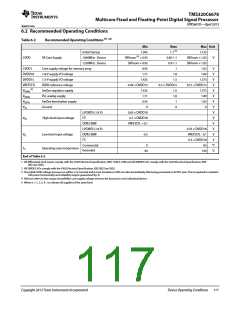
6.2 Recommended Operating Conditions
Table 6-2
Recommended Operating Conditions (1) (2)
Min
1.045
Nom
1.1 (3)
Max Unit
Initial Startup
1.155
CVDD
SR Core Supply
1000MHz - Device
1250MHz - Device
SRVnom (4) × 0.95
SRVnom × 0.95
0.95
0.85-1.1
SRVnom × 1.05
V
0.9-1.1
SRVnom × 1.05
CVDD1
Core supply voltage for memory array
1.8-V supply I/O voltage
1.5-V supply I/O voltage
DDR3 reference voltage
SerDes regulator supply
PLL analog supply
1
1.05
V
V
V
V
V
V
V
V
V
V
V
V
V
V
°C
°C
DVDD18
DVDD15
VREFSSTL
1.71
1.8
1.89
1.425
1.5
1.575
0.49 × DVDD15
1.425
0.5 × DVDD15
0.51 × DVDD15
(5)
VDDRx
1.5
1.8
1
1.575
1.89
1.05
0
VDDAx
VDDTx
VSS
1.71
SerDes termination supply
Ground
0.95
0
0
LVCMOS (1.8 V)
I2C
0.65 × DVDD18
0.7 × DVDD18
VREFSSTL + 0.1
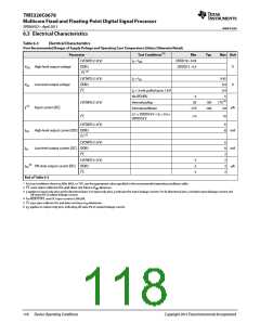
VIH
High-level input voltage
DDR3 EMIF
LVCMOS (1.8 V)
DDR3 EMIF
I2C
0.35 × DVDD18
VREFSSTL - 0.1
0.3 × DVDD18
85
VIL
TC
Low-level input voltage
-0.3
Commercial
Extended
0
Operating case temperature
-40
100
End of Table 6-2
1 All differential clock inputs comply with the LVDS Electrical Specification, IEEE 1596.3-1996 and all SERDES I/Os comply with the XAUI Electrical Specification, IEEE
802.3ae-2002.
2 All SERDES I/Os comply with the XAUI Electrical Specification, IEEE 802.3ae-2002.
3 The initial CVDD voltage at power on will be 1.1V nominal and it must transition to VID set value immediately after being presented on VCNTL pins. This is required to maintain
full power functionality and reliability targets guaranteed by TI.
4 SRVnom refers to the unique SmartReflex core supply voltage set from the factory for each individual device.
5 Where x = 1, 2, 3, 4... to indicate all supplies of the same kind.
Copyright 2013 Texas Instruments Incorporated
Device Operating Conditions
117

 TI [ TEXAS INSTRUMENTS ]