TMS320C6672
Multicore Fixed and Floating-Point Digital Signal Processor
SPRS708C—February 2012
www.ti.com
7.23 Timers
The timers can be used to: time events, count events, generate pulses, interrupt the CPU and send synchronization
events to the EDMA3 channel controller.
7.23.1 Timers Device-Specific Information
The TMS320C6672 device has ten 64-bit timers in total. Timer0 and Timer1 are dedicated to each of the two
CorePacs as a watchdog timer and can also be used as general-purpose timers. Each of the other eight timers can also
be configured as a general-purpose timer only, with each timer programmed as a 64-bit timer or as two separate
32-bit timers.
When operating in 64-bit mode, the timer counts either VBUS clock cycles or input (TINPLx) pulses (rising edge)
and generates an output pulse/waveform (TOUTLx) plus an internal event (TINTLx) on a software-programmable
period.
When operating in 32-bit mode, the timer is split into two independent 32-bit timers. Each timer is made up of two
32-bit counters: a high counter and a low counter. The timer pins, TINPLx and TOUTLx are connected to the low
counter. The timer pins, TINPHx and TOUTHx are connected to the high counter.
When operating in watchdog mode, the timer counts down to 0 and generates an event. It is a requirement
that software writes to the timer before the count expires, after which the count begins again. If the count ever
reaches 0, the timer event output is asserted. Reset initiated by a watchdog timer can be set by programming ‘‘Reset
Type Status Register (RSTYPE)’’ on page 139 and the type of reset initiated can set by programming ‘‘Reset
Configuration Register (RSTCFG)’’ on page 140. For more information, see the 64-bit Timer (Timer 64) for KeyStone
Devices User Guide in ‘‘Related Documentation from Texas Instruments’’ on page 69.
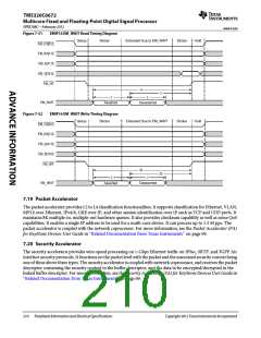
7.23.2 Timers Electrical Data/Timing
The tables and figure below describe the timing requirements and switching characteristics of Timer0 through
Timer9 peripherals.
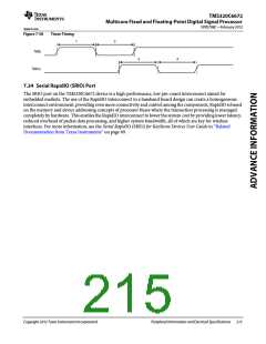
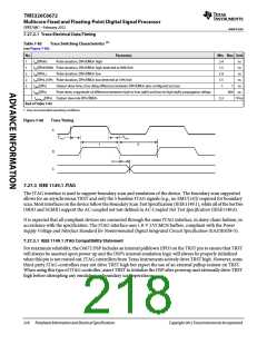
Table 7-81
Timer Input Timing Requirements (1)
(see Figure 7-58)
No.
Min
12C
12C
Max
Unit
ns
1
2
tw(TINPH)
tw(TINPL)
Pulse duration, high
Pulse duration, low
ns
End of Table 7-81
1
C = 1 ÷ CORECLK(N|P) frequency in ns.
Table 7-82
Timer Output Switching Characteristics (1)
(see Figure 7-58)
No.
Parameter
Pulse duration, high
Min
12C - 3
12C - 3
Max
Unit
ns
3
4
tw(TOUTH)
tw(TOUTL)
Pulse duration, low
ns
End of Table 7-82
1
C = 1 ÷ CORECLK(N|P) frequency in ns.
214
Peripheral Information and Electrical Specifications
Copyright 2012 Texas Instruments Incorporated

 TI [ TEXAS INSTRUMENTS ]