TMS320C6672
Multicore Fixed and Floating-Point Digital Signal Processor
SPRS708C—February 2012
www.ti.com
7.22 Management Data Input/Output (MDIO)
The management data input/output (MDIO) module implements the 802.3 serial management interface to
interrogate and controls up to 32 Ethernet PHY(s) connected to the device, using a shared two-wire bus. Application
software uses the MDIO module to configure the auto-negotiation parameters of each PHY attached to the GbE
switch subsystem, retrieve the negotiation results, and configure required parameters in the GbE switch subsystem
module for correct operation. The module is designed to allow almost transparent operation of the MDIO interface,
with very little maintenance from the core processor. For more information, see the Gigabit Ethernet (GbE) Switch
Subsystem for KeyStone Devices User Guide in ‘‘Related Documentation from Texas Instruments’’ on page 69.
Table 7-79
MDIO Timing Requirements
See Figure 7-56
No.
Min
Max
Unit
1
2
3
4
5
tc(MDCLK)
tw(MDCLKH)
tw(MDCLKL)
Cycle time, MDCLK
400
180
180
10
ns
ns
ns
ns
ns
ns
Pulse duration, MDCLK high
Pulse duration, MDCLK low
tsu(MDIO-MDCLKH) Setup time, MDIO data input valid before MDCLK high
th(MDCLKH-MDIO)
tt(MDCLK)
Hold time, MDIO data input valid after MDCLK high
Transition time, MDCLK
10
5
End of Table 7-79
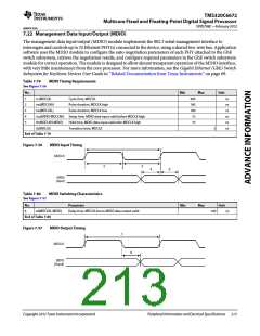
Figure 7-56
MDIO Input Timing
MDCLK
2
3
4
5
MDIO
(Input)
Table 7-80
See Figure 7-57
MDIO Switching Characteristics
Parameter
No.
Min
Max
Unit
6
td(MDCLKL-MDIO)
Delay time, MDCLK low to MDIO data output valid
100
ns
End of Table 7-80
Figure 7-57
MDIO Output Timing
1
MDCLK
6
MDIO
(Ouput)
Copyright 2012 Texas Instruments Incorporated
Peripheral Information and Electrical Specifications 213

 TI [ TEXAS INSTRUMENTS ]